- 6 -
- 7 -
EN - WORKTOP TRUE CUT
EN - WORKTOP TRUE CUT
Pivoting the Jig
• Remove pins and cams
• Pivot the jig to the offset scribe line on the
marked worktop
• Clamp jig in position and remove Worktop
True Cut device
• Begin cut -
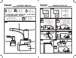
(Fig. 6)
Take care not to slide Worktop True
Cut from position
Be sure to follow jig manufactures
manual
Cutting Out of Square Male
Joint – (Fig. 7a – 7c)
• Setting up for out of square Male joint
-
(Fig. 7a)
• Routing roughing cuts x5 for out of square
Male joint -
(Fig. 7b)
• Routing finishing cut for out of square Male
joint -
(Fig. 7c)
MAINTENANCE
Please use only Trend original spare parts and
accessories.
The jig has been designed to operate over a
long period of time with a minimum of
maintenance. Continual satisfactory operation
depends upon proper tool care and regular
cleaning.
Cleaning
• Regularly clean the jig with a soft cloth.
Lubrication
• Your jig requires no additional lubrication.
Storage
• After use store jig in its packaging.
ENVIRONMENTAL PROTECTION
Recycle raw materials instead of disposing
as waste.
Packaging should be sorted for
environmental-friendly recycling.
The product and its accessories at the end of
their life should be sorted for environmental
friendly recycling.
GUARANTEE
All Trend products guaranteed against any
defects in either workmanship or material,
except products that have been damaged
due to improper user or maintenance.
16. Please ensure children and visitors away
from tools and work area.
17. All tools have a residual risk so must
therefore be handled with caution.
18. Only use Trend original spare parts and
accessories.
If you require further safety advice, technical
information, or spare parts, please call Trend
Technical Support or visit
www.trend-uk.com
ITEMS ENCLOSED & DESCRIPTION
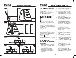
OF PARTS – (Fig. 1)
A
Pivot block
B
Clamp block
C
Handle
D
Handle reposition button
E
Worktop True Cut
Pins and cams not included.
ITEMS REQUIRED
• 1/2” Plunge router
• 30mm Guide bush
• Trend 12mm thick worktop jig
• Hand tools
OPERATION
Whenever clamps are used, ensure
they do not foul the router path and that
they are securely tightened.
In order to prevent breakout of the
laminate, rotation of the cutter
and feed direction of the router must
always be into the postform edge of
worktop.
Ensure worktop is held securely to
trestles. Ensure jig is clamped securely
to worktop and placed at a comfortable
height.
Release plunge on router at end of
each cut.
Support waste piece to avoid injury
or damage to equipment.
Example of and How to
Measure Acute Angle – (Fig. 2)
Example of and How to
Measure Obtuse Angle – (Fig. 3)
Worktop True Cut Position Set up
and Clamp – (Fig. 4a – 4c)
For standard worktop jigs:
• Insert pins and push up to edge of worktop.
Place the Worktop True Cut into jig slot as
indicated and position up to the postformed
edge.
-
(Fig. 4a)
For Trend KWJ750P and KWJ900
worktop jigs:
• Insert pins and cams and push up to edge
of worktop. Place the Worktop True Cut into
jig slot as indicated and position up to the
postformed edge. -
(Fig. 4b)
• Once the Worktop True Cut touches the
worktop edge, gently tighten the handle -
(Fig. 4c)
• Remove pins and/or cams -
(Fig. 4d)
Take care not to move the jig set
when tightening the handle.
Offset Marking – (Fig. 5a – 5d)
• When female is in position place male into
position and measure gap between the
two-front face
-
(Fig. 5a)
• Clamp Worktop True Cut to your worktop
jig -
(Fig. 5b)
• Select relevant cams and pins for desired
inset
• Take measurement from 5a and transfer
to the male piece of worktop. Please note
when marking your worktop measurement
to factor in the guide bush and cutter
distance -
(Fig. 5c)
• Place jig onto worktop and pivot jig so that
it follows your cut line -
(Fig. 5d)


