


PIVOT FRAME JIG
-14-
workpieces (eg. rustic nameplates).
A particular advantage of the ‘open’ construction
of the pivot frame, is the ability to see the
workpiece clearly, with the router assembly riding
well above the workpiece. This can be of
particular advantage for work against a template,
where the cut needs to be ‘stopped’ by visual
inspection.
Guided Planing Mode
This machining mode is essentially an extension
of the foregoing arrangement and permits
planing of long work, together with a facility for
machining parallel grooves or edge-mouldings.
It requires a flat work surface and two straight-
edged battens of constant thickness, which may
be fixed to a flat work surface (cramping is quite
suitable), such that the straight edges are
separated by a fixed distance and are parallel.
The jig is adjusted so that the flanges of the
nylon shoes ride on the battens and the smaller
diameter of the shoes bears against the edges
of the battens. Ride-height is determined initially
by the depth of the battens, but may be modified
by suitable arrangement of the shoe spacers.
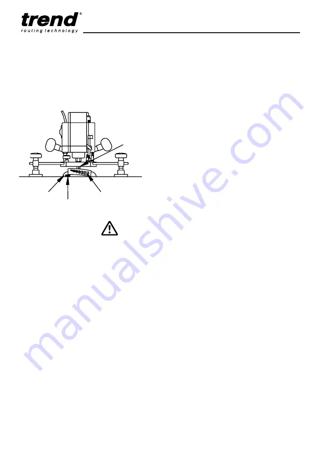
The workpiece may be attached to the worktop
by fillets of hot-melt glue. Where the workpiece
is uneven on both surfaces (e.g. it may be
twisted), it may be packed with small pieces of
veneer at the high spots, until it cannot be
rocked on the worktop; the glue fillets may then
be applied.
It is recommended that the largest diameter
bottom-cut router cutter available is used for this
operation. The use of routers limited to 1/4"
diameter shanks will reduce the possibilities but,
for example, a 25.4mm (1") diameter cut will be
obtained from straight two-flute cutter Trend Ref.
4/08X1/4TC and a 30mm cut from scribing ovolo
cutter Trend Ref. 6/5X1/4TC, both available with
1/4" shank.
To begin, the jig should be moved over the work
with the cutter stationary, in order to find the
highest point; depth of cut may then be set with
reference to this point. It is recommended that
several passes are made over the work with a
very small depth of cut (no greater than 0.5mm),
gradually clearing the high-spots and eventually
arriving at a flat smooth surface.
The router may be left to slide freely on its rods
and guided by means of its plunge knobs for this
operation, since it will stay in place at any set
position, provided the cut is light. If the cut is too
deep, the router may take control and pull itself
across the work off-line.
For the final cut in particular, which should be no
greater than 0.2mm, the router should be locked
on the rods for each pass, and moved across
the work by means of the locking knobs on a
pivot bar and not by the handles on the router
itself. This will eliminate any tendency for over-
depth cutting due to hand-pressure ‘springing’
the guide rods.
Another possibility with the system is that of
machining straight parallel grooves, either
continuous or stopped, with any of a number of
straight or profiling cutters.
It is not wise to rely on accurate tracking of the
system along both parallel battens for work of
this nature, where positional accuracy of the
router is of importance. The work is better
carried out by preferential pressure on one
batten only.
Moreover, it is perfectly possible for even a stout
batten to spring slightly in the centre under
pressure, if it is cramped at the ends only. An
additional cramp or two towards the centre will
CUTTER
FLAT-BOTTOMED
STOCK
WARPED
PACKING
VENEER
FILLET
GLUE
Summary of Contents for PFJ/SET/1
Page 1: ...PIVOT FRAME JIG...


