Getting Started
2-5
T
ABLE
2-2.
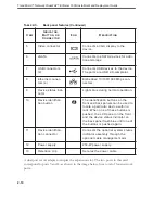
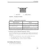
Front panel features
I
TEM
I
NDICATOR
,
B
UTTON
,
OR
C
ONNECTOR
I
CON
D
ESCRIPTION
1
Power-on indicator,
power button
The power button turns the device on
and off. The indicator lights up when
the device is on.
Tip:
To force the device to shut
down, press and hold the power
button for five seconds.
2
NMI button
The nonmaskable interrupt (NMI)
button is used to troubleshoot soft-
ware and device driver errors. This
button can be pressed using the end
of a paper clip. Use this button only if
directed to do so by qualified support
personnel.
3
Video connector
Connects to a monitor; can be used
to locally access and configure the
device.
4
Hard drive activity
indicator
Lights up when the hard drive is in
use.
5
Diagnostic indica-
tors (4)
The diagnostic indicators aid in trou-
bleshooting hardware-related issues
with technical support.
6
Device status indi-
cator
Lights blue during device system
operation.
Summary of Contents for viruswall enforcer 1500i
Page 1: ......
Page 7: ...Trend Micro Network VirusWall Enforcer 1500i Installment and Deployment Guide vi...
Page 13: ...Trend Micro Network VirusWall Enforcer 1500i Installment and Deployment Guide xii...
Page 30: ...Getting Started 2 11 FIGURE 2 7 Standard four port configuration Port 1 Port 3 Port 4 Port 2...
Page 59: ...Trend Micro Network VirusWall Enforcer 1500i Installment and Deployment Guide 3 20...
Page 78: ......

