background image

44

NX-Platform Hardware Installation and Safety

To attach the Console port connection

Describes how to attach the console port connection.
1. Connect the RJ-45 null modem cable to the Console port on the unit.
2. Connect the other end of your cable (standard-sized female DB-9 connector) to your VT100-compatible

terminal or your computer.

Use the following terminal settings for the Console port:
• Baud rate: 115.2 Kbps
• Character size: 8 bits
• Parity: None
• Stop Bits: One
• Flow Control: None

To attach the Management Processor connection

Describes how to attach the management processor connection.
1. Connect one end of the Category 5 Ethernet cable to the port labeled MGMT located on the front

panel.

2. Connect the other end of the Ethernet cable to your network.

This enables remote management.

To attach network connections

Describes how to attach the network connections.
1. Attach the cable for incoming traffic to the A port on the segment.
2. Attach the cable for outgoing traffic to the B port on the segment.
3. Connect the cables to the appropriate ports on your network router.
For more information about TippingPoint NX-Platform IPS configuration and network connections, refer

to the 

Local Security Manager User Guide

.

Check LEDs

When you connect power to the IPS, the system completes a series of component checks.
It then displays LEDs to show the status of each component. Refer to 

Model requirements 

  on page 35 for

more information about the LEDs.

Summary of Contents for TippingPoint NX-Platform

Page 1: ...NX Platform Hardware Installation and Safety 5998 1403 October 2016 ...

Page 2: ...ts and services are set forth in the express warranty statements accompanying such products and services Nothing herein should be construed as constituting an additional warranty Trend Micro Incorporated shall not be liable for technical or editorial errors or omissions contained herein TippingPoint the TippingPoint logo and Digital Vaccine are trademarks or registered trademarks of Trend Micro In...

Page 3: ...cture 4 Security Management System SMS 5 SMS server 6 SMS client 6 Intrusion Prevention System devices 7 IPS local clients 8 Core Controller 8 High availability 9 Threat Suppression Engine 9 Threat Management Center 10 Hardware safety and compliance 12 Safety and compliance requirements 12 Safety guidelines and warnings 12 Cautions 13 Warnings 13 Installation warnings 13 Parts warnings 14 ...

Page 4: ...ew 20 Chassis overview 20 Chassis features 23 Power button 23 Fans and power supplies 24 External storage card 24 Ports 24 Chassis LEDs 25 I O modules 26 Bypass I O modules 29 BIOM connectors and speeds 30 Notable BIOM behavior 30 Link transitions 31 Optical insertion loss 31 Default I O module configuration settings 32 Hot swapping I O modules 32 I O module hot swapping guidelines 33 Module LEDs ...

Page 5: ...ions 41 Add I O modules 42 Attach cables 43 To attach the Console port connection 44 To attach the Management Processor connection 44 To attach network connections 44 Check LEDs 44 Setup wizard 45 Power supply and fan modules 46 NX Platform AC power supply 46 NX Platform DC power supply 47 NX Platform fans 49 Installing the power cord retention bracket 51 Power cord retention bracket 51 Installing...

Page 6: ...Hardware Installation and Safety About the external storage card 54 External storage card commands 54 Connector and pinout specifications 56 RJ 45 COM console 56 RJ 45 Ethernet connectors 57 Pluggable transceivers 58 ...

Page 7: ...networking concepts and the following standards and protocols TCP IP UDP ICMP Ethernet Simple Network Time Protocol SNTP Simple Mail Transport Protocol SMTP Simple Network management Protocol SNMP Related documentation A complete set of product documentation for the TippingPoint Intrusion Prevention Systems is available online The product document set generally includes conceptual and deployment i...

Page 8: ...ut Code Text typed at the command line Monospace italic font Code variables Command line variables Monospace bold font Emphasis of file and directory names system output code and text typed at the command line Messages Messages are special text that is emphasized by font format and icons Warning Alerts you to potential danger of bodily harm or other potential harmful consequences Caution Provides ...

Page 9: ...bout how to perform a task more easily or more efficiently Contacting support Contact the TippingPoint Technical Assistance Center TAC by using any of the following options Email support tippingpoint support trendmicro com Phone support North America 1 866 681 8324 International See https tmc tippingpoint com ...

Page 10: ... an intuitive management interface This topic includes the following information TippingPoint architecture on page 4 Security Management System SMS on page 5 Intrusion Prevention System devices on page 7 Core Controller on page 8 High availability on page 9 Threat Suppression Engine on page 9 Threat Management Center on page 10 TippingPoint architecture The TippingPoint System uses a flexible arch...

Page 11: ...ion and the Threat Management Center SMS Management Client Java based application for Windows or Linux workstations used to manage your TippingPoint system Graphical User Interface GUI Dashboard Command Line Interface CLI The SMS communicates with managed devices that are installed in your network The SMS architecture also includes the following components Threat Management Center TMC Centralized ...

Page 12: ...ted and imported to devices which can be reviewed and modified by local clients If a device is managed by the SMS Server the local clients cannot modify settings Filter and software distribution Monitors and maintains the distribution and import of filters Digital Vaccine packages and software for the TippingPoint Operating System and SMS client The SMS client and Central Management Server can dis...

Page 13: ...ors with launch capabilities into the targeted management applications that provide global command and control of TippingPoint Included in the SMS dashboard display are the following items Entries for the top five filters triggered over the past hour in various categories A graph of triggered filters over the past 24 hours The health status of devices Update versions for software of the system Thr...

Page 14: ...e management access This access requires access from a supported web browser Internet Explorer Mozilla Firefox and Netscape Using the LSM you have a graphical display for reviewing searching and modifying settings The GUI interface also provides reports to monitor the device traffic triggered filters and packet statistics Command Line Interface CLI Command line interface for reviewing and modifyin...

Page 15: ...ure With INHA a failure puts the device into Layer 2 Fallback mode and permits or blocks traffic on each segment In TNHA multiple IPS devices are synchronized so that when one device experiences a system failure traffic is routed to the other device with no interruption in intrusion prevention services SMS high availability provides continuous administration through an active passive SMS system co...

Page 16: ...licious traffic and attacks on your network The filters provide the following protections Application Protection Defend against known and unknown exploits that target applications and operating systems Attack Protection filters Detect and block traffic known to be malicious suspicious and to have known security implications These filters include vulnerabilities and exploits filters Security Policy...

Page 17: ...NX Platform Hardware Installation and Safety 11 Traffic Management filters Protect the network by shielding against IP addresses or permitting only a set of IP addresses ...

Page 18: ...ormation refer to the TippingPoint Hardware Safety and Compliance Guide available on the TMC and included with your product Safety guidelines and warnings Provides important information and safety warnings Before you start the installation procedures read this entire section for important information and safety warnings The warnings in this section have been localized to 28 languages in the Tippin...

Page 19: ...stalled according to the manufacturer s instructions You must also consider the weight of any other device installed in the rack Make sure that the chassis cooling fans run continuously while the system is powered Caution Make sure all cards are completely connected to the backplane Improper connections can disrupt system operation Caution When using a DC power supply be sure to replace the plasti...

Page 20: ...equires short circuit overcurrent protection to be provided as part of the building installation Install only in accordance with national and local wiring regulations Warning Do not work on the system or connect or disconnect cables during periods of lightning activity Warning To prevent the unit from overheating do not operate it in an area that exceeds the maximum recommended ambient temperature...

Page 21: ...ng magnets or magnetic fields Warning Keep all liquids and dust away from the product Warning All optical interfaces and sources connected to this product and its modules must only use Class 1 lasers Using any other Laser Class source can create hazardous conditions to the user Warning This product can contain Class 1 lasers Do not stare into the laser beam or view it directly with optical instrum...

Page 22: ...k load the rack from the bottom to the top with the heaviest component at the bottom of the rack Ensure that the unit is positioned properly on the rack There should be three inches clearance at the ventilation openings When mounting this unit in an enclosed or multi rack assembly the operating ambient temperature of the rack may be greater than the room ambient temperature Ensure that the maximum...

Page 23: ...ge from Electromagnetic Static Discharge ESD can occur when electronic components are improperly handled Its results can be complete or intermittent system failures Proper ESD protection is required whenever you handle equipment It is not necessary to open the product chassis to add or remove any components The following general grounding guidelines apply in the event that a power supply module or...

Page 24: ... with the black levers Unpack the product Describes how to unpack the product Each chassis is securely packaged in a shipping box Caution ESD can damage the product if you do not take necessary precautions Installation and maintenance personnel should be properly grounded using ground straps to eliminate the risk of ESD damage to the equipment All cards and modules are subject to ESD damage whenev...

Page 25: ...mage If you think any equipment might be damaged contact your freight provider for how to lodge a damage claim Also contact your TippingPoint sales or field representative for instructions Note The shipping materials are recyclable Please save for later use or dispose of them appropriately ...

Page 26: ...installation you should also obtain the IPS Command Line Interface Reference After installing the components complete the TippingPoint Setup Wizard as part of the installation and configuration procedures This topic includes the following information Chassis overview on page 20 I O modules on page 26 Model requirements on page 35 Technical specifications on page 36 Hardware installation and config...

Page 27: ...Point S2600 NX Up to 3Gbps TippingPoint S5200 NX Up to 5Gbps TippingPoint S6200 NX Up to 10Gbps TippingPoint S7100 NX Up to 15Gbps TippingPoint S7500 NX Up to 20Gbps Figure 2 TippingPoint NX Platform IPS front panel no modules installed 1 Blank module 2 Stack Master LED 3 Stack LED 4 Bypass LED 5 System Health LED 6 CFast Card 7 Console Port top and Management Port bottom 8 Power Button ...

Page 28: ...ed 1 6 Segment Gig T NX module 2 6 Segment GbE SFP NX module 3 4 Segment 10GbE SFP NX module 4 1 Segment 40GbE QSFP NX module 5 Stack Master LED 6 Stack LED 7 Bypass LED 8 System Health LED 9 CFast Card 10 Console Port top and Management Port bottom 11 Power Button Figure 4 TippingPoint NX Platform IPS back panel ...

Page 29: ... 2 7 Fan module 3 8 Fan module 4 9 Fan module 5 Chassis features Provides links to the various NX Platform chassis features Power button on page 23 Fans and power supplies on page 24 External storage card on page 24 Ports on page 24 Power button The power button is located on the front panel The power button light indicates its current status No light Device is powered off ...

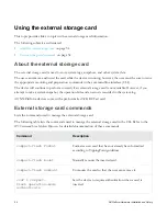
Page 30: ...he external storage card is used to store system logs snapshots and other system data The user can remove and insert the card while the device is running however the user must be sure to issue the appropriate mounting and preparation commands in the command line interface CLI Refer to Using the external storage card on page 54 for more information Ports Describes the ports of the NX Platform IPS T...

Page 31: ...ctive or is active at 10 Mbps or 100 Mbps Blinking amber Data traffic is passing Activity Off No traffic is passing Chassis LEDs The following table describes states of each chassis LED Port type Color Description Off Unit is not stack master or not member of a stack Green Unit is stack master Yellow Unit is secondary to master Stack Master Blinking yellow Stack election is in progress Off Unit is...

Page 32: ...les Describes the standard and bypass I O modules The TippingPoint NX Platform IPS supports both standard I O modules and bypass I O modules see the following tables for fiber and copper components Note Only optical transceiver modules including SFP SFP and QSFP available from TippingPoint have been validated to achieve optimal performance with TippingPoint products Other vendor devices are not su...

Page 33: ... a 40GbE module from a slot and then insert a different module type that is not another 40GbE module For a list of transceivers supported on NX Platform device modules refer to the TippingPoint Operating System TOS Release Notes Version 3 9 0 NX Platform devices support the following standard I O modules Module name Ports Port speed Part number 6 Segment Gig T NX Gig T 12 Copper 10 100 1000 Mbps T...

Page 34: ...term interface ethernet 1 1A negotiate OR conf term interface ethernet 1 1A no negotiate conf term interface ethernet 1 1A linespeed 1000 You can revert to SFP by inserting an SFP into the 10GbE module and entering the following command in the command line interface conf term interface ethernet 1 1A no negotiate conf term interface ethernet 1 1A linespeed 10000 NX Platform devices support the foll...

Page 35: ...ngle Mode Fiber LC type 1 10Gbps TPNN0074 Bypass I O modules The NX Platform IPS supports a range of bypass I O modules BIOMs which combine the IPS segment interfaces with mechanical bypass switches for high availability purposes The BIOMs offered for the NX Platform support various interface speed and connectivity types including copper or fiber 1Gbps or 10Gbps and long range or short range The B...

Page 36: ...ach Multimode 850nm fiber network segments The NX IPS 2 segment 1Gbps Fiber LR Bypass Module JC879A can accept two1Gbps Long Reach Single mode 1310nm fiber network segments The NX IPS 2 segment 10Gbps Fiber LR Bypass Module JC881A can accept two10Gbps 1Gbps Long Reach Single mode 1310nm fiber network segments Notable BIOM behavior When deploying BIOMs ensure that traffic passes in the normal inspe...

Page 37: ...s Insertion loss for optical BIOMs is higher than for standard I O modules This normal drop in signal power occurs because of the presence of optical switches and the two duplex connections on the module s front panel Unlike standard I O modules insertion loss for a BIOM link happens twice once when the signal enters the module s duplex connection and once when it exits the connection In addition ...

Page 38: ... settings themselves cannot be changed These default settings are as follows Module configuration defaults No action necessary to restart the module No action necessary to delete the slot configuration Network port configuration defaults Auto negotiation is enabled Line speed set to the maximum for this type of port Duplex set to full Port enabled Segment configuration defaults Segments are named ...

Page 39: ...le ports and segments on the slot become absent and unavailable However any policy related configuration for these ports does not change when the bay configuration is erased and must be manually cleaned up by the user When a module is inserted into a slot or restarted the system software performs the following evaluation When the IPS boots up the evaluation is performed for every module installed ...

Page 40: ...rough a reboot BIOMs that are installed with the power off are taken out of bypass mode automatically by the system software To change a BIOM from bypass mode to normal mode administratively From the CLI type high availability zero power no bypass ips slot slot number From the LSM menu click System High Availability and select Normal in the Zero Power HA External field For more information on maki...

Page 41: ... user Off Module in bypass Bypass Status Green Module in normal mode not in bypass Model requirements Provides links to topics that describe power and cabling requirements The following topics describe power and cabling requirements for the TippingPoint NX Platform IPS Power requirements on page 35 Cabling requirements on page 36 Power requirements Describes the power requirements of the NX Platfo...

Page 42: ...ently supported on NX Platform devices refer to the TippingPoint Operating System TOS Release Notes Version 3 8 0 You can also receive a Right Angle IEC Receptacle power cord for the device You can use this cable for connecting power to the device in cases where you might not have enough room for a straight power connection cable This cable helps in situations when you need to install a device in ...

Page 43: ...to 70 C Storage Altitude No degradation up to 10 000 feet 3048 m Humidity 5 to 95 non condensing External interfaces 1x1GbE copper management port 1x1 RJ 45 console port 1 external storage card drive Data port interfaces vary depending on the installed I O modules See I O modules on page 26 Note The pluggable transceiver ports do not include SFP SFP or QSFP transceivers Software specifications Pro...

Page 44: ...configuration procedures This topic includes the following information TippingPoint NX Platform IPS chassis on page 38 Attach cables on page 43 Check LEDs on page 44 Setup wizard on page 45 TippingPoint NX Platform IPS chassis Provides the task topics that describe how to install the IPS device To install the IPS you must do the following Determine total rack space on page 38 Attach the device to ...

Page 45: ...ing the unit in the rack If the rack is partially filled load the rack from the bottom to the top with the heaviest component at the bottom of the rack If you plan to expand your system to include additional TippingPoint systems in the future allow space in the rack for additions During the initial installation keep in mind the weight distribution and stability of the rack Rack mounting options Yo...

Page 46: ... the chassis to the rack with the standard rack mounting ears loosely mount the seismic brackets into the holes of the rack mounting ears with the provided SEMS screws four on each side included Then secure the seismic brackets to the rear rack post with screws six on each side not included Finally tighten all screws including the SEMS screws that fasten both pairs of brackets together Figure 7 Re...

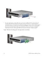
Page 47: ...ost with screws six on each side not included Figure 8 Mid mounting Power supply and I O module connections After you have bolted the IPS to the rack attach the power supply AC connections Depending on the TOS your device is running insert your I O modules as described in the following section before turning the power on For devices running TOS V 3 5 x I O modules must be added with your device tu...

Page 48: ...wer cord retention bracket and a cable management assembly For instructions on installing these accessories refer to Installing the power cord retention bracket on page 51 Add I O modules Describes how to add I O modules to your IPS device For a complete list of the I O modules available for the TippingPoint NX Platform IPS see I O modules on page 26 The device comes with four blank modules insert...

Page 49: ...t Handle all I O modules with care The bypass modules contain mechanical switches that are very sensitive to handling when not installed in the system Network disruption can occur if handled improperly Figure 11 Inserting an I O module Attach cables Describes which connections to use to access the OBE setup wizard During setup use the management processor connection or the console port to access t...

Page 50: ... 5 Ethernet cable to the port labeled MGMT located on the front panel 2 Connect the other end of the Ethernet cable to your network This enables remote management To attach network connections Describes how to attach the network connections 1 Attach the cable for incoming traffic to the A port on the segment 2 Attach the cable for outgoing traffic to the B port on the segment 3 Connect the cables ...

Page 51: ...yed on your COM port terminal The wizard prompts you to perform basic configuration tasks and periodically input information After you run the setup you can further configure your system using subsequent setup commands through the Command Line Interface CLI See the IPS Command Line Interface Reference for detailed instructions ...

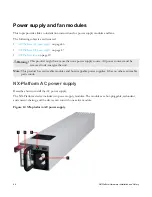
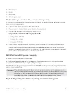
Page 52: ...arning This product might have more than one power supply source All power sources must be removed to de energize the unit Note This product has serviceable modules and hot swappable power supplies It has no other serviceable parts inside NX Platform AC power supply Describes how to install the AC power supply The NX Platform device includes two power supply modules The modules are hot pluggable r...

Page 53: ...rs back on when the power is reconnected if power was off the device stays off when the power is reconnected If necessary power on the device with the button on the front of the chassis NX Platform DC power supply Describes how to install the DC power supply DC power supplies are available for the TippingPoint N Platform Consult your TippingPoint account contact for more information if you require...

Page 54: ...ire to the chassis ground strap mounting The wire should be crimped with a ring lug 3 Locate the power input terminal block on the back of the module 4 Attach the 12 AWG DC power wires to the power input terminal block labeled 48V and RTN The power wires should be crimped with lug spades to ensure a secure connection 5 Connect the other side of the power cable to the SELV power source The power so...

Page 55: ...int NX Platform devices Figure 14 NX Series fan 1 Removal Latch 2 Handle 3 Status LED Green The fan is running normally Off The fan is faulty Note The fan LED will also be off when the system is booting up and when a fan has just been replaced Ensure that the system is fully booted when checking status After you have identified the faulty fan assembly follow this procedure to replace the fan 1 Rem...

Page 56: ...on and Safety 4 Install the new fan assembly by sliding the fan into the open slot The latch slides into place automatically After you insert the fan module the fan LED blinks for up to two minutes while the system verifies the fan RPM ...

Page 57: ...cket on page 51 Removing the bracket on page 53 Power cord retention bracket Provides a description and image of the power cord retention bracket The power cord retention bracket part number 5066 1202 helps reduce strain on the power cord and power supply outlets Figure 15 Power cord retention bracket Installing and using the bracket Shows an NX Platform IPS with the power cord retention bracket i...

Page 58: ...cket against the back surface of the chassis 2 Slide the bracket over the two shoulder rivets on the back of the chassis The spring loaded plunger in the center of the bracket slides into place Using the power cord retention bracket Describes how to attach the power cord to the retention bracket Follow this procedure to attach the power cord to the retention bracket 1 Fold the power cable and slid...

Page 59: ... Hardware Installation and Safety 53 Removing the bracket If you need to remove one of the brackets pull the spring loaded plunger in the middle of the bracket and slide the bracket up and off the shoulder rivets ...

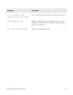
Page 60: ...age card is not available However if you attempt to take a system snapshot the operation fails and an error is recorded in the system log All NX Platform devices come with a pre formatted 32 GB CFast card External storage card commands Lists the commands used to manage the external storage card The following table lists the commands used to manage the external storage card in the CLI Refer to the ...

Page 61: ...eration mode auto mount Sets the device to automatically mount cards when inserted show compact flash Displays whether the card is mounted and if so its model number serial number revision number capacity operation mode and mount status show conf compact flash Shows the card s operation mode ...

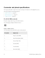
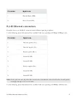
Page 62: ...COM console on page 56 RJ 45 Ethernet connectors on page 57 Pluggable transceivers on page 58 RJ 45 COM console Describes and provides an image of the RJ 45 connector The following figure displays the RJ 45 connector Figure 17 RJ 45 connector The following table shows the RJ 45 console connector pinouts Pin number Signal name 1 Request to Send RTS 2 Data Terminal Ready DTR 3 Transmit Data TxD 4 Gr...

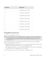
Page 63: ...n your RJ 45 device is operating in 10Mbps 100Mbps mode Pin number Signal name 1 Transmit positive Tx 2 Transmit negative Tx 3 Receive positive Rx 4 Ground GND 5 Ground GND 6 Receive negative Rx 7 Ground GND 8 Ground GND Note These ports can auto negotiate their mode and can automatically detect whether they should operate in straight through or cross over mode Use the following pinout information...

Page 64: ...ptimal performance TippingPoint products Other vendor devices are not supported Using other vendor devices could be detrimental to proper operation of the TippingPoint system For a list of transceivers currently supported on NX Platform device modules refer to the TippingPoint Operating System TOS Release Notes Version 3 9 0 TippingPoint NX platform models that use one or more 4 Segment 10GbE SFP ...

Page 65: ...NX Platform Hardware Installation and Safety 59 Fiber input Signal Left side Transmit Right side Receive ...

Reviews: