Trelawny TPG650 Operation & Maintenance Manual Download Page 6

Maintenance 

 
Carefully tilt the machine backwards 
to rest on its handle bar. 
 
Place  a  heavy  object  (10kg  sand 
bag,  etc.)  across  the  upper  part  of 
the  handle  bar  or  rope  down  for 
additional security. 
 
Remove  any  build  up  of  material 
from  around  the  grinding  disc,  the 
holding pins,


springs and nuts. 

 
Using  a  Soft  Headed  Mallet  apply 
force  to  the  outside  edge  of  the  
Quick Release tools hitting the tools 
inwards.  When  hitting  the  tool  be 
careful not to hit the diamond or the 
metal  bonding.  Repeat  for  rest  of 
tools on the Machine. 
 
To  replace  simply  slide  the  Quick 
Release  tools  into  the  Taper  Slot. 
Apply  force  with  use  of  a  soft  
headed  mallet  striking  the  tools 
outwards.  Repeat  for  remaining 
tools. 
 
Remove  the  weight  from  the  handle 
bar and/or remove the security rope. 
Carefully  return  the  machine  to  its 
upright position and move the handle 
bar to is normal working position and 
secure with the two pins. 
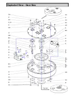
 

Plate Removal:


Push  down  on  one  of  the  holding 
pins nuts by hand and rotate the pin 
90deg,  repeat  with  the  two  pins. 
Remove the disc. 
 
Note that the centres of the discs are 
different  depending  on  the  direction 
the discs rotate:- 
(Flower 

Part No 365.5835F)

(Triangle 

Part No 365.5835T) 

 
Refit the Tool Plates, these can only 
be fitted onto the correct hub. 
Push  down  on  one  of  the  holding 
pins nuts by hand and rotate the pin 
90deg, repeat with the two pins.  
 
Ensure  that  the  pin  has  located  into 
its  recess,  and  that  the  disc  is 
secure. 
 
Repeat with the other plates. 
 
 
Re-adjust the dust cover rubber ring. 

Shut Down 

Simply  Press  the  Black  „STOP‟ 
Button. 
After  the  machine  has  completely 
cooled,  clean  off  any  concrete  dust 
from  external  components  and 
remove  any  heavy  build  up  of 
concrete  dust  from  inside  the  front 
dust skirt. 
 
Take  care  when  using  hoses  or 
pressure  washers  and  clean  within 
the dust skirt area only. 
 
Do  not  hose  down  any  of  the 
external surfaces. 
 
Do not  to allow  water to  be directed 
at  or  splashed  onto  the  electric 
motor  or  any  of  the  electrical 
components. 
 
Once  clean  and  dry,  cover  the 
machine  to  protect  it  and  store  the 
grinder in a dry place.


Grinding Tool 
Replacement 

Switch off the machine and allow the 
grinding  head  tools  to 

cool 

completely

,  disconnect  machine 

from its power supply. 
 

IMPORTANT 

Do  not  use  a  mix  of  old  and  new 
grinding  tools,  this  will  cause  rapid 
wear  of  the  new  tools  and  could 
cause  the  machine  to  become 
uncontrollable,  unstable  and 
dangerous in use. 
 
Drain all water from the tank. 
 
Place the machine on a flat and level 
surface. 
 
Remove  the  additional  weight  from 
the  machine if fitted. 
 
Remove  the  retaining  pin  from  the 
handle  bar  height  adjustment  pin 
and  raise  the  handle  bar  to  a  near 
upright position (vertical). 
 
Replace  the  adjustment  pin  and 
secure with the retaining pin. 

Old Screw Fit System:


After removing the plate from the 
machine (Using the steps provided 
previously). 


Remove  the  three  star  screws 
retaining  each  of  the  tools  to  the 
disc. 
(Torx or TX male (size 30 bit)) 
 
Replacement  is  the  reverse  of 
stripping,  the  diamond  tools  are 
handed  and  cannot  be  fitted  the 
wrong way round. 
 
Tighten  the  tool  screws  initially  by 
hand, finally  tighten using  a wrench, 
do not over tighten. 
 

Belt:


A  belt  replacement  guide  can  be 
f o u n d   o n l i n e   a t   h t t p : / /
trelawnyspt.com/  or  can  be  sent  by 
request 


Machine Storage 

Long period storage: 
over 3months 

Allow  the  machine  to 

cool 

completely.


Clean outside of machine.  
 
Remove  any  build  up  of  material 
from inside of grinding disc area. 
 
Inspect  the  grinding  tools  for  wear; 
replace any worn parts as required. 
 
Ensure  that  the  machine  is 
completely dry. 
 
Cover the machine to protect it. 
 
Store the machine in a dry place. 


Summary of Contents for TPG650

Page 1: ...OPERATION MAINTENANCE TPG650 PLANETARY FLOOR GRINDER ...

Page 2: ...ituated at the rear of the machine BE VERY CAREFUL WITH HOT COMPONENTS The diamond tools and tool heads can become very hot in use Always use gloves when changing or replacing the grinding segments DO NOT OPERATE ELECTRIC VERSIONS IN WET CONDITIONS CAUTION THIS MACHINE IS HEAVY It weighs 260kg 573lbs Do not lift this machine manually use a hoist or crane with the grinder securely fastened to a pal...

Page 3: ...ick Release Medium Bond For Medium Hardness concrete 365 5503 30 Grit Single Quick Release Hard Bond For Soft Concrete or for very rough concrete 365 5501 2 30 Grit Double Quick Release Soft Bond For Hard Concrete 365 5502 2 30 Grit Double Quick Release Medium Bond For Medium Hardness concrete 365 5503 2 30 Grit Double Quick Release Hard Bond For Soft Concrete or for very rough concrete 365 5504 2...

Page 4: ...02A 200 Grit Resin Bond 365 5604A 400 Grit Resin Bond 365 5608A 800 Grit Resin Bond 365 5618A 1500 Grit Resin Bond 365 5635A 3000 Grit Resin Bond 350 5666 Polishing Adapter Plate Used to attach the Polishing Tools to the quick release plate 365 5745 3 Segment Polishing Plate Set of 3 Used to attach Polishing Tools For use only on the TPG650 540 ...

Page 5: ...t have a minimum core wire size of 2 5mm2 cross section area Maximum length of cable 30 meters Starting Check over the whole area to be worked It is important to check the area to ensure that there are no obstacles or protrusions that will damage the machine or the tools This is a flat surface grinder If the surface is very bumpy or uneven consider using the Trelawny Floor Planer to level the floo...

Page 6: ...e the front dust skirt Take care when using hoses or pressure washers and clean within the dust skirt area only Do not hose down any of the external surfaces Do not to allow water to be directed at or splashed onto the electric motor or any of the electrical components Once clean and dry cover the machine to protect it and store the grinder in a dry place Grinding Tool Replacement Switch off the m...

Page 7: ...Exploded View Gear Box ...

Page 8: ... Central Axis G05 365 2248H Gasket Ø120 11 365 2250D Axis G06 365 2255E Gasket Ø200 x Ø 116 18 365 2248F Box Bottom Plate S01 853 0816 CS Head Screw M8 x 16 19 365 2255B Box Top Plate S02 853 0830 CS Head Screw M8 x 30 20 365 2255A Box Cylinder S03 852 0616 Button head Screw M6 x 16 38 365 2250N Central Axis Pulley S04 853 1025 CS Head Screw M10 x 25 39 365 2250C Axis Pulley 40 365 2250G Tension B...

Page 9: ...Exploded View Plate Holder ...

Page 10: ...260D Compress ring 2 piece set 31E 365 2260E Torque Cover 53A 365 2260M Driving Disk Central Block 1 53B 365 2260N Driving Disk Central Block 2 AV1 365 9146A Anti Vibration Element 1 AV2 365 9146B Anti Vibration Element 2 AV3 365 9146C Anti Vibration Element 3 AV4 365 9146D Anti Vibration Element 4 K01 365 2260F Keyway L01 365 2260J Compress Spring for disk holding pin S01 853 0816 CS Head Screw M...

Page 11: ...Exploded View Machine Assembly T01 T02 T03 T05 ...

Page 12: ...2243 Oil Seal Ø130 x Ø160 x 12 12A 365 2241A Motor Coupling part on Motor Shaft 12B 365 2241B Flex Element 12C 365 2241C Motor Coupling part on Central Axis Motor 365 9575 Motor S05 852 0812 Button Head Screw M8 x 12 S06 806 0650 Socket Cap Screw M6 x 50 S07 853 0825 CS Head Screw M8 x 25 S08 831 1230 Hexagon H T bolt M12 x 30 T01 365 2235 Handle T02 365 2220 Water Container T03 365 2200 Frame T04...

Page 13: ...M22 K10 365 9570C Contact Block M22 LED W 365 9570D LED Element M22 PV 365 9570E Emergency Stop Button M22 XZK GB99 365 9570F E stop label 33x50mm M22 WRK3 365 9570G 3 Position 60 Rotary Switch M22 R4K7 365 9570H Rotary Potentiometer M22 DDL WS X1 X0 365 9570I Start Stop Button M22 T DD 365 9570J Transparent diaphragm ...

Page 14: ...t Check if there is a signal of failure on the screen of the frequency converter See below Grinder is slow or erratic Check for heavy build up of dirt on the grinding disk Check that the segments are not worn down and that they are securely fixed to the disk The grinding discs turn but the main disc is stationary The top belt has broken contact your nearest reseller The motor runs but nothing turn...

Page 15: ...then please do not hesitate to contact us Your comments are both important and appreciated Trelawny SPT Ltd Trelawny House 13 Highdown Road Sydenham Industrial Estate Leamington Spa Warwickshire CV31 1XT United Kingdom Telephone 44 0 1926 883781 Fax 44 0 1926 450352 Email sales trelawny co uk Website www trelawnyspt com TSPT UK 2009 Part No 735 6650 issue 3 SURFACE PREPARATION TECHNOLOGY All right...

Reviews: