background image

32 • T-MAXX

2.5

2

1.5

1

0.5

0

0

10

20

30

40

60

70

80

90

100

50

 Wheel Force (lb)

Wheel Travel (mm)

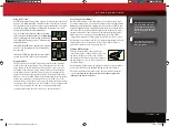
 Wheel Force vs. Wheel Travel

Lower Mount 1, Upper Mount 0
Lower Mount 2, Upper Mount 0
Lower Mount 1, Upper Mount A
Lower Mount 2, Upper Mount A
Lower Mount 3, Upper Mount A
Lower Mount 4, Upper Mount A
Lower Mount 1, Upper Mount B
Lower Mount 2, Upper Mount B
Lower Mount 3, Upper Mount B
Lower Mount 4, Upper Mount B

Less Firm

More Firm

Lower Mount 4

Lower Mount 3

Lower Mount 2

Lower Mount 1

TUNING ADJUSTMENTS

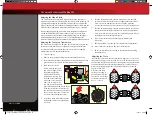
For easier access to the 
rear-most shock mounting 
screw, remove the one end 
of the rear turnbuckle. In the 
front, remove the suspension 
pin from the lower front 
suspension arm to gain easier 
access to the lower shock 
mounting screws.

Shock Mounting Positions

Big bumps and rough terrain require a softer 

suspension with the maximum possible 
suspension travel and ride height.  Racing on 
a prepared track or on-road use requires a 
lower ride height and firmer, more progressive 
suspension settings. The more progressive 
suspension settings help reduce body roll 
(increased roll stiffness), dive during braking, and 
squat during acceleration.

The innermost upper shock mounting position 

(0) on the shock tower is intended for use with 
the first generation T-Maxx suspension arms.  
With the second generation arms (2.5-powered T-Maxx), position (0) can be 
used for tuning with the inner pair of lower shock mounting positions on the 
arm (1,2). It is not compatible with lower shock mounting positions 3 and 4 
on the second generation (2.5-powered T-Maxx) arms. Upper shock mounting 
position (A) should generally be used with lower shock mounting positions 
1 and 2. Generally, upper shock mounting position (B) should be used with 
lower shock mounting positions 3 and 4. Other combinations may be used to 
achieve individualized suspension settings.

Lower Shock Mounting Positions


In the out-of-the-box configuration, the shocks are installed in position (A) on 

the shock tower and position (2) on the lower suspension arm. This setting 
allows for moderate suspension travel and ride height. The more vertical 
position of the shocks allows for lower shock progression and the soft, plush 
feel that’s characteristic of the T-Maxx.

The outer pair of holes on the lower suspension arm should be used to lower 

the ride height of the T-Maxx and increase the spring force (at the wheel). 
This setting will improve high-speed cornering on smoother terrain by 
lowering the center of gravity and providing a firmer suspension feel. Body 
roll, brake dive, and squat will be reduced.

Spring rate

 (at the wheel) increases as the lower shock mounting position 

is moved from position (1) to position (4). This is equivalent to using stiffer 
springs. Use higher spring rate settings for flatter terrain with smaller and 
fewer bumps and lower spring rate settings for bigger bumps.

Ride height

 decreases as the lower shock mounting position is moved from 

position (1) to position (4). Each pair of lower shock mounting holes (1,2 and 
3,4) has equal ride height. Use lower ride height for high-speed cornering 
and flat terrain, and when racing on relatively smooth tracks. Increase the 
ride height for rougher terrain and tracks.

Upper Shock Mounting Positions 

The upper shock mounting positions will have the opposite affect on the 

suspension that the lower shock mounting positions.

Spring rate 

(at the wheel) increases as the upper shock  

mounting position is moved from position (A) to position (B). 

Ride height

 is not affected by changes in the upper shock  

mounting position.

Use the chart below to see the effect of the various shock mounting positions.  

The horizontal length of the lines indicates the amount of suspension travel.  
The angle or slope of the lines indicates the spring rate (at the wheel). 

49104-1-KC2230-R00-T-Maxx-Operating.indd   32

10/30/14   5:10 PM

Summary of Contents for T-MAXX 49104-1

Page 1: ...6200 TRAXXAS WAY McKINNEY TX 75070 1 888 TRAXXAS 141030 KC2230 R00 MODEL 49104 1 MODEL 49104 1 owner s manual owner s manual 49104 1 KC2230 R00 T Maxx Operating indd 36 37 10 30 14 2 13 PM...

Page 2: ...new T Maxx 3 4 5 6 7 8 14 29 30 33 35 BEFORE YOU PROCEED SAFETY PRECAUTIONS TOOLS SUPPLIES AND REQUIRED EQUIPMENT ANATOMY OF THE T MAXX QUICK START GETTING UP TO SPEED TRAXXAS TQ 2 4GHz RADIO SYSTEM...

Page 3: ...ands of registered members in our online community at Traxxas com Traxxas offers a full service on site repair facility to handle any of your Traxxas service needs Maintenance and replacement parts ma...

Page 4: ...well ventilated area Never run the engine indoors Do not operate your T Maxx at night or anytime your line of sight to the model may be obstructed or impaired in any way Never operate your T Maxx in c...

Page 5: ...information on radio system batteries see Use the Right Batteries on page 10 8 AA alkaline batteries Traxxas Top Fuel see page 18 Small flat blade screwdriver for tuning 1 8 inch blade After run oil t...

Page 6: ...urnbuckle Throttle Brake Servo Receiver Box Transmission Air Filter Tuned Pipe Header TRX 2 5 Racing Engine see pg 15 for details Pressure Line Fuel Line EZ Start Motor EZ Start Plug Bulkhead Shock To...

Page 7: ...5 Decal and Install the body See page 8 14 Break in your engine See page 24 You will need to use the body during break in so it s best to apply any additional decals before you use the body Follow th...

Page 8: ...ottle Servo Channel 3 Shifting Servo TQ 2 4GHz TRANSMITTER Steering Trim Shifting Switch Throttle Trigger Steering Wheel Power Switch Battery Compartment Set Button Red Green Status LED Applying The D...

Page 9: ...ginal rechargeable hobby pack NiCad batteries have very high current handling high capacity and can last up to 1000 charging cycles Good charging procedures are required to reduce the possibility of d...

Page 10: ...your model it is important to stop at the first sign of weak receiver batteries Visible warning signals include sluggish steering response and shortened radio range INSTALLING TRANSMITTER BATTERIES Yo...

Page 11: ...ng only Reversing a channel reverses the direction of the corresponding servo For example if you turn the steering wheel to the right and the model turns left Channel 1 would need to be reversed to co...

Page 12: ...es out When the throttle trigger is pushed all the way forward the brake should lock 7 Operate the shift button on the transmitter and check for rapid operation of the shifting servo Push the shift bu...

Page 13: ...TRANSMITTER LED CODES LED Color Pattern Name Notes Solid green Normal Driving Mode See page 11 for information on how to use the transmitter controls Slow red 0 5 sec on 0 5 sec off Binding See this...

Page 14: ...premature engine wear and failure is lack of care and maintenance break in The TRX 2 5 Racing Engine is manufactured to exacting tolerances and requires a specially designed break in procedure to acc...

Page 15: ...Mount Low Speed Needle Throttle Arm Clutch Bell Flywheel Carburetor Air Intake Fuel Intake High Speed Needle Idle Speed Adjustment Screw EZ Start Plug Positive Wire Negative Wire Fuel Line Fuel Tank T...

Page 16: ...he engine that holds the reciprocating assembly Cooling fins The cooling fins are milled into the cylinder head and crankcase and cause heat to be drawn away from the engine Heat is removed when it di...

Page 17: ...ngine to have the required compression for combustion Port Ports are openings in the sleeve that allow atomized fuel to enter the combustion chamber and burned exhaust gases to exit The shape and loca...

Page 18: ...ed to run best within a range of nitro percentages How the engine is ported the size of the combustion chamber and other factors determine how much nitro can be efficiently used in the engine The TRX...

Page 19: ...ter anytime the engine is running Even if you can t see dirt on the filter it is present inside the foam after any amount of run time If you exceed the recommended cleaning intervals your engine will...

Page 20: ...needles are there to adjust how much fuel is made available for the carburetor to mix with the available air atomization The Fuel Mixture Needles The amount of fuel metered and atomized by the carbure...

Page 21: ...engine running to assess what minor adjustments may be required to compensate for fuel temperature and altitude Adjustments are usually made in 1 8 or 1 16 turn increments If the engine sticks at top...

Page 22: ...een LED on the charger indicates the charge progress 3 Disconnect the battery when charging is complete When the battery is fully charged the LED will light solid green The battery will be warm in you...

Page 23: ...nk the engine over at the appropriate RPM to keep the piston from sticking at top dead center TDC A new engine will typically have a tight fit between the piston and the top of the sleeve This is a ta...

Page 24: ...e or clean your air filter after break in Follow the instructions exactly for each of the first 5 tanks of fuel Starting Your TRX 2 5 Racing Engine for the First Time Before you start your TRX 2 5 Rac...

Page 25: ...rly empty shut off the engine and refuel From here on you do not need to let the engine cool between tanks Tank 4 1 Driving procedure Gently pull the throttle trigger to full throttle over a 3 second...

Page 26: ...cool down If the water takes a long time or does not evaporate at all then the engine is too cool We do not recommend that you operate your engine below 35 F If you insist on running your vehicle belo...

Page 27: ...setting will extend engine component life Low Speed Fuel Mixture Adjustment The low speed mixture is always set after the high speed needle is correctly adjusted The low speed mixture is set using the...

Page 28: ...almost in direct proportion to air temperature Assuming you tuned the engine for the same maximum performance each day the engine will run about twenty degrees hotter when it s ninety degrees outside...

Page 29: ...mmediately Move the vehicle and then continue driving Never turn off the radio system while the engine is running The truck could run out of control Forward and Reverse Operation Forward and reverse g...

Page 30: ...le As you slowly turn the primary gear shaft counterclockwise the first set screw that becomes visible holds the two speed mechanism on to the shaft Do not loosen this screw The second set screw is th...

Page 31: ...hock angle or spring rates are made You can compensate for ride height changes by changing the pre load spacers on the shocks Adjusting the Suspension The T Maxx has adjustable suspension so that it m...

Page 32: ...ized suspension settings Lower Shock Mounting Positions In the out of the box configuration the shocks are installed in position A on the shock tower and position 2 on the lower suspension arm This se...

Page 33: ...on how the slipper clutch was adjusted and how the T Maxx was used If the slipper will not tighten or you are seeing signs of wear on the face of the gear then the pegs should be replaced Piston sleev...

Page 34: ...EZ Start button for several seconds to clear the engine of excess fuel Do not look into the glow plug hole while the engine is spinning or you could spray fuel into your face 5 Turn the model over an...

Page 35: ...g and idling Only lean the fuel mixture just until the engine will run and idle reliably and then proceed with the break in The contents of different brands of fuel other than Traxxas Top Fuel in comb...

Page 36: ...6200 TRAXXAS WAY McKINNEY TX 75070 1 888 TRAXXAS 141030 KC2230 R00 MODEL 49104 1 MODEL 49104 1 owner s manual owner s manual 49104 1 KC2230 R00 T Maxx Operating indd 36 37 10 30 14 2 13 PM...

Reviews: