background image

42 • Revo

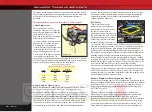
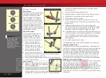
This advanced tuning guide will take you one step further into the cutting
edge technology that has been designed into Revo. Follow the instructions
provided here to take advantage of Revo’s maximum performance
potential. 

Suspension and Alignment Settings

Caster Adjustment

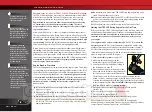
The caster angle of the front
suspension may be used to adjust the
understeer (push)/oversteer handling
characteristics of the model.
Generally, increasing the caster angle
will move the truck towards an
oversteer condition (more traction on
the front tires, less on the rear tires).
Decreasing the caster angle will
create a tendency towards understeer
(pushing in the turns). From the
factory, the front suspension is set to
a caster angle of 10-degrees. The rear
caster angle is not adjustable. The
caster angle of the front suspension can be adjusted from 5° to 15°. Adjust
the caster by positioning the caster adjustment shims on the upper control
arms of the front suspension as shown in the table below:

Caster Angle, and Bump Steer

Bump steer is unwanted change in the steering angle of the front wheels 
as the suspension travels up and down. It can result in unstable and
unpredictable handling. Bump steer is affected by the position of the outer
toe link end on the axle carrier. From the factory, the toe links are positioned
so that bump steer is virtually eliminated (about 3/100 of a degree through
the entire range of travel). When the caster angle is changed, the outer toe
link end should be repositioned on the axle carrier to maintain zero bump
steer geometry. Adjustment is achieved using the shims and hollow balls
provided with the vehicle. Refer to the Bump Steer Elimination chart on

page 43,  and look up your caster angle setting to find the correct position
for the outer toe links. Positioning the toe-links correctly will maintain the
original factory geometry and eliminate the unwanted steering angle
changes caused by bump steer.

Roll Center

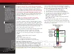
There are two holes on the
bulkheads to mount each upper
suspension arm. The roll center of
the vehicle can be raised by
mounting the upper control arm in
the lower of the two holes. This will
effectively increase the roll stiffness
of the vehicle (similar to installing
swaybars). Adding roll resistance to
one end of the vehicle will tend to add traction to the opposite end. For
example, increasing roll resistance in the rear by installing the upper arms
in the lower holes will provide more traction for the front wheels and
potentially more steering. Installing the upper arms in the lower holes on
the front and rear will increase overall roll resistance without changing the
handling balance. The arms are installed in the upper position from the
factory to make the truck easier and more forgiving to drive and less likely
to traction roll in turns. The lower holes should be reserved for track tuning.

Note:

When the upper suspension arms are moved to the lower holes, the

front outer toe link ends and the rear toe control links should be
repositioned to eliminate bump steer. Refer to the Bump Steer Elimination
chart on page 43, and look up your suspension combination (caster angle
and roll center position) to find the correct position for the front outer toe
links and the rear toe control links. Adjustment is achieved using the shims
and hollow balls provided with the vehicle.

Rockers (Progressive Rate/ Suspension Travel)

One of the most exciting aspects of Revo’s suspension is the inboard shock
(damper) arrangement that uses pivoting rockers to translate vertical wheel
travel into linear shock motion. The rockers can be changed to increase or
decrease the maximum wheel travel and also to change the progressive
rate of the suspension. 

The progressive rate determines how much the force at the wheel
produced by the springs being compressed (wheel force) will vary with
suspension travel (or vertical travel of the wheel). On a progressive
suspension arrangement, the wheel force will increase at a faster and faster
rate as the suspension is compressed. It feels as though the shock spring
gets progressively stiffer the more you compress the suspension. On a
linear suspension arrangement, the wheel force increases linearly as the

Caster

5.0°
7.5°

10.0°
12.5°
15.0°

In Front of 

Hinge Pin Boss

None

One
Two

Three

Four

Behind 

Hinge Pin Boss

Four

Three

Two
One

None

Number and Position of Caster 

Adjustment Shims (Front Upper Control Arm)

Caster adjustment shims (2 front, 2 rear)

Vertical

Ground plane

10°

Upper Control Arm

Upper Mounting Holes

Upper Control Arm

Lower Mounting Holes

Upper Control Arm

Upper Mounting Holes

Upper Control Arm

Lower Mounting Holes

Advanced Tuning adjustments


Summary of Contents for Revo 5310

Page 1: ...MODEL 5310 owner s manual...

Page 2: ...e time to read through these instructions This manual contains all the necessary set up break in tuning and operating procedures that allow you to unlock the incredible performance and adjustment pote...

Page 3: ...Technical assistance is also available at www Traxxas com You may also e mail customer support with your question at support Traxxas com Join hundreds of Traxxas R C enthusiasts in our online communi...

Page 4: ...ot during use Be careful not to touch the parts especially when refueling or stopping the engine Prolonged exposure to the engine exhaust can be harmful Avoid breathing the engine exhaust Always run y...

Page 5: ...ng charger is recommended for best performance and longest battery life Inexpensive wall chargers may also be used with very good results For more information see Use the Right Charger on page 26 NiCa...

Page 6: ...details Pressure Line Fuel Line EZ Start Motor EZ Start Plug Bulkhead under chassis Body Mount Post Spur Gear Chassis Slipper Clutch Driveshaft Half Shaft On Off Switch Shift Rod Antenna Mount Access...

Page 7: ...habit of turning the transmitter on first and off last 9 Check servo operation See page 17 Make sure the throttle shifting and steering servos are working correctly 10 Range test the radio system See...

Page 8: ...ons show the process with the wheels removed 8 Revo Gluing the Tires and Decorating your Revo 1 Remove a wheel from Revo using the larger 8mm end of the glow plug universal wrench 2 Use your thumb to...

Page 9: ...ve monitors the voltage of the on board RX Power Pack The Function LED will flash red if the battery voltage is too low Antenna Throttle Neutral Adjust Steering Wheel Throttle Trim Steering Trim Rever...

Page 10: ...viation for Nickel Metal Hydride This is the type of rechargeable battery used to power the radio system in the model These batteries are generally more efficient with less memory effect than NiCad ba...

Page 11: ...ight does not indicate the charge level of the RX Power Pack installed in the model Revo 11 The Traxxas TQ 3 Radio System CH 3 CH 2 CH 1 Use the Right Batteries Your transmitter uses AA batteries Use...

Page 12: ...the back of the case to allow convenient out of the way wall mounting The RX Power Charger can be powered by our optional D C car adapter It features a tangle free extra long wire and integrated fuse...

Page 13: ...he top of the tube to secure the antenna wire 5 On the transmitter always fully extend the telescoping antenna when running your Revo Make a habit of holding the transmitter so that the antenna points...

Page 14: ...and braking 70 30 Allows more throttle travel 70 and less brake travel 30 50 50 is the required setting for Revo with the TRX 2 5R Racing Engine Electronic Throttle Trim The electronic throttle trim...

Page 15: ...hold the SET button until the Function LED flashes green twice and then release the button immediately You are now in programming mode 4 Pull the transmitter throttle trigger to the full throttle pos...

Page 16: ...engine is running The on off switch in the model only turns the receiver on and off It does not turn off the engine Always use new or freshly charged batteries for the transmitter and make sure the on...

Page 17: ...le trigger is pushed all the way forward the brake should lock 7 Operate the shift button on the transmitter and check for rapid operation of the shifting servo Push the shift button down for forward...

Page 18: ...le break in procedures such as idling the engine on the bench for several tanks of fuel or simply running the engine with a very rich fuel mixture for the first 4 tanks of fuel will not achieve the be...

Page 19: ...e Throttle Arm Clutch Bell Flywheel Carburetor Air Intake Fuel Intake High Speed Needle Idle Speed Screw EZ Start Plug Positive Wire Negative Wire Fuel Line Fuel Tank Tuned Pipe Exhaust Tip Pressure L...

Page 20: ...e Cooling fins The cooling fins are molded into the cylinder head and crankcase and cause heat to be drawn away from the engine Heat is removed when it dissipates into the air passing across the cooli...

Page 21: ...Piston The piston is the internal engine part that is attached to the upper end of the connecting rod and moves up and down in the cylinder sleeve The precise fit between the piston and the sleeve cre...

Page 22: ...at Traxxas spent over 2 years developing the TRX 2 5R Racing Engine No one knows more about the specific fuel requirements of Traxxas engines than Traxxas engineers We strongly urge you not to take ch...

Page 23: ...in the bottom of the filter body Pull out the foam element 3 Clean the filter parts by thoroughly washing all three pieces of the filter assembly in hot soapy water dishwashing detergent works well Re...

Page 24: ...fuel more fuel molecules to maintain the correct air fuel ratio Warmer air is less dense fewer air molecules and therefore needs less fuel to maintain the correct air fuel ratio The tuning needles ar...

Page 25: ...e settings have been pre set from the factory to typical break in settings Do not readjust your carburetor from the factory settings until after the engine is started and running and you have been abl...

Page 26: ...igned for 7 2 volt battery packs Charge the battery according to the charger manufacturer s directions 1 Press the tab in the end of the battery compartment door to open 2 Plug a fully charged 7 2 vol...

Page 27: ...f The Engine Turning off the switch for the radio will not shut off the engine To shut off the engine use the shut off clamp on the fuel line Simply squeeze the clamp closed to shut off the fuel suppl...

Page 28: ...urface Apply all throttle and braking actions gently Abrupt acceleration or braking could cause the engine to stall unnecessarily Special break in fuels are not recommended Use the same fuel you plan...

Page 29: ...count Then gently apply the brake to stop Count the two seconds out while accelerating one thousand one one thousand two and then stop Repeat this starting and stopping procedure until the second tank...

Page 30: ...erformance High Speed Fuel Mixture Adjustment With the engine warm and running at a rich setting gradually lean the high speed fuel mixture in 1 16 turn increments Make several high speed passes with...

Page 31: ...r to its original position Fine Tuning the Carburetor After fine tuning your TRX 2 5R Racing Engine at the end of the break in procedure no major adjustments to the fuel mixture are usually necessary...

Page 32: ...then the engine is too cool We do not recommend that you operate your engine below 35 degrees Fahrenheit If you insist on running your vehicle below 35 degrees just make sure you are aware that nitro...

Page 33: ...ould run out of control Forward and Reverse Operation Forward and reverse gears are selected with the shift button located in the transmitter handle grip The switch is normally in the down or forward...

Page 34: ...ion travel see illustration If suspension sag is severe and requires a large increase of the spring pre load to compensate then a firmer spring should be used Firmer springs supplied must be used when...

Page 35: ...scosity oil will increase damping Lowering the viscosity of the oil will cause the suspension damping to be reduced Damping should be increased with higher viscosity oil if the model is bottoming easi...

Page 36: ...ic camber is the camber angle at the wheel when the vehicle is set at its normal stationary ride height The suspension pivot balls located in the axle carriers adjust the static camber The pivot balls...

Page 37: ...is adjusted by loosening the spring loaded locknut on the slipper shaft Use the supplied 8mm open end metric wrench To tighten or loosen the slipper nut insert the 2 0mm hex wrench into the hole in t...

Page 38: ...gear clutch bell gear mesh for Revo is 0 1mm To set the gear mesh place a strip of standard letter A4 size copy or printer paper about 0 1mm thick between the mating teeth Loosen the two horizontal en...

Page 39: ...ulder bolts that are used to secure the brake pads to the transmission housing may need to be adjusted periodically as the brake material wears down They should be tightened so a 0 50mm 020 gap exists...

Page 40: ...e maintenance Inspect the connecting rod after 3 gallons of fuel have been used Slipper clutch pads friction material Under normal use the friction material in the slipper clutch should wear very slow...

Page 41: ...the engine The engine will most likely start and run for a few seconds as it uses up any fuel remaining in the engine and fuel lines 4 Once the engine stops clean the outside of the engine with compre...

Page 42: ...rs Adding roll resistance to one end of the vehicle will tend to add traction to the opposite end For example increasing roll resistance in the rear by installing the upper arms in the lower holes wil...

Page 43: ...n compressing the spring in order to maintain proper ride height then the next stiffer spring should be used The chart below demonstrate the effect of the various rocker arms on wheel force as the sus...

Page 44: ...move the piston up and down always keeping it submerged in oil to release the air bubbles Let the shock sit for a few minutes to allow any remaining air bubbles to surface 10 Slowly thread the upper...

Page 45: ...ront LF left front RR right rear and LR left rear Note The exhaust system must be removed to access the rear rocker arms 1 Remove shock absorbers Remove the screws that secure the shocks to the chassi...

Page 46: ...lean out 20 Clearing your frequency 10 Clutch bell 19 45 mesh 38 Combustion chamber 20 27 Compression 21 Connecting rod 20 maintenance 40 Cooling fins 20 Crankcase 19 20 Crankshaft 19 20 Crashing 33 C...

Page 47: ...1 Ride height 34 Rockers 6 42 installing 45 Roll hoop 6 Rollover 33 RPM 21 RX Pack 10 Safety 4 5 8 23 41 Servo chart 15 Servo reversing switches 9 15 Servo Saver 39 Shift button 9 Shift rod 6 Shifting...

Page 48: ...owner s manual 1 100 Klein Road Plano Texas 75074 1 888 TRAXXAS 040428 MODEL 5310...

Reviews: