15
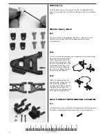
STEP C-8
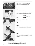
Assemble the upper control arms as shown. The center-to-center dis-
tance should be 42mm.
Set all of these assembled linkage components aside.
BAG D DRIVE SHAFT
STEP D-1
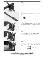
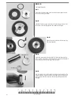
Drive shafts: In bag D, find the sub-bag containing the drive shaft com-
ponents. From the “Tools” bag, find the U-joint assembly tool. Separate
the parts into like groups.
STEP D-2
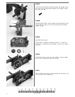
Find (1) stub axle, (1) metal u-joint ball (spider), and one internal-splined
drive shaft (female).
STEP D-3
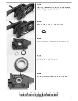
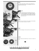
Begin assembly by inserting one pin of the metal U-joint ball into one
ear of the drive shaft joint.
STEP D-4
Use the u-joint assembly tool to snap the remaining pin into the opposite
ear. Apply pressure down while pushing so that both ears will spread
and reduce the possibility of stretching or breaking an ear. Wrap a rag
around the half shaft and the tool to help hold it.
42mm
U-joint assembly tool


