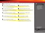
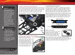
Traxxas 020334940711 Owner'S Manual Download Page 10

10 • DRAG SLASH

Applying the Decals

The main decals for your model 
have been applied at the 
factory. Additional decals are 
printed on self-adhesive clear 
mylar and are die-cut for easy 
removal. Use a hobby knife to 
lift the corner of a decal and lift 
it from the backing. 

To apply the decals, place one 
end down, hold the other end 
up, and gradually smooth the 
decal down with your finger 
as you go. This will prevent air 
bubbles. Placing both ends of 
the decal down and then trying 
to smooth it out will result in 
air pockets.  Look at the photos 
on the box for typical decal 
placement.

TRAXXAS TQ

i

 RADIO & VELINEON POWER SYSTEM
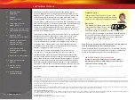
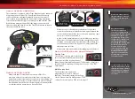
INTRODUCTION

Your model includes the latest Traxxas TQi 2.4GHz transmitter with 
Traxxas Link

 Model Memory. The transmitter’s easy-to-use design 

provides instant driving fun for new R/C enthusiasts, and also offers 
a full complement of pro-level tuning features for advanced users 
– or anyone interested in experimenting with the performance of 
their model. The steering and throttle channels feature adjustable 
Exponential, End Points, and Sub-Trims. Steering and braking Dual-
Rate are also available. Many of the next-level features are controlled 
by the Multi-Function knob, which can be programmed to control 
a variety of functions. The detailed instructions (page 28) and Menu 
Tree (page 31) included in this manual will help you understand and 
operate the advanced functions of the new TQi radio system. For 
additional information and how-to videos, visit Traxxas.com.

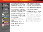
RADIO AND POWER SYSTEM TERMINOLOGY

Please take a moment to familiarize yourself with these radio and 
power system terms. They will be used throughout this manual.
A detailed explanation of the advanced terminology and features 
of your new radio system begins on page 28.

2.4GHz Spread Spectrum 

– This model is equipped with the latest 

R/C technology. Unlike AM and FM systems that require frequency 
crystals and are prone to frequency conflicts, the TQi system 
automatically selects and locks onto an open frequency and offers 
superior resistance to interference and “glitching.” 

BEC (Battery Eliminator Circuit)

 - The BEC can either be in the 

receiver or in the ESC. This circuit allows the receiver and servos 
to be powered by the main battery pack in an electric model. 
This eliminates the need to carry a separate pack of 4 AA 
batteries to power the radio equipment.
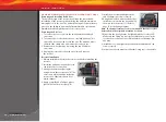
Brushless Motor

 - A D/C brushless motor replaces the brushed 

motor’s traditional commutator and brush arrangement with 
intelligent electronics that energize the electromagnetic 
windings in sequence to provide rotation. Opposite of a brushed 
motor, the brushless motor has its windings (coils) on the 
perimeter of the motor can and the magnets are mounted to the 
spinning rotor shaft.

Cogging 

- Cogging is a condition sometimes associated with 

brushless motors. Typically, it is a slight stutter noticed when 
accelerating from a stop. It happens for a very short period as 
the signals from the electronic speed control and the motor 

synch with each other. The VXL-3s electronic speed control is 
optimized to virtually eliminate cogging. 

Current

 - Current is a measure of power flow through the 

electronics, usually measured in amps. If you think of a wire as a 
garden hose, current is a measure of how much water is flowing 
through the hose.

ESC (Electronic Speed Control)

 - An electronic speed control is the 

electronic motor control inside the model. The VXL-3s electronic 
speed control uses advanced circuitry to provide precise, digital 
proportional throttle control. Electronic speed controls use 
power more efficiently than mechanical speed controls so that 
the batteries run longer. An electronic speed control also has 
circuitry that prevents loss of steering and throttle control as the 
batteries lose their charge.

Frequency band

 - The radio frequency used by the transmitter to 

send signals to your model. This model operates on the 2.4GHz 
direct-sequence spread spectrum.

kV Rating

 - Brushless motors are often rated by their kV number. 

The kV rating equals no-load motor rpm with 1 volt applied. The 
kV increases as the number of wire turns in the motor decreases. 
As the kV increases, the current draw through the electronics 
also increases. The Velineon 3500 motor is a 3500 kV motor 
optimized for the best speed and efficiency in lightweight 1/10 
scale models.

LiPo

 - Abbreviation for Lithium Polymer. Rechargeable LiPo 

battery packs are known for their special chemistry, which 
allows extremely high energy density and current handling in a 
compact size. These are high performance batteries that require 
special care and handling. LiPo battery packs are for advanced 
users only.

mAh

 – Abbreviation for milliamp hour, a measure of the capacity 

of the battery pack. The higher the number, the longer the 
battery will last between recharges.

Neutral position

 - The standing position that the servos seek 

when the transmitter controls are at the neutral setting.

NiCad

 - Abbreviation for nickel-cadmium. The original 

rechargeable hobby pack, NiCad batteries have very high current 
handling, high capacity, and can last up to 1000 charging cycles. 
Good charging procedures are required to reduce the possibility 
of developing a “memory” effect and shortened run times.

8

8

Summary of Contents for 020334940711

Page 1: ...owner s manual MODEL 94076 4 ...

Page 2: ...ng in the shortest time possible If you are an experienced R C enthusiast you will find it helpful and fast Be sure and read through the rest of the manual to learn about important safety maintenance and adjustment procedures Turn to page 9 to begin 3 BEFORE YOU PROCEED 4 SAFETY PRECAUTIONS 6 ANATOMY OF THE DRAG SLASH 7 TOOLS SUPPLIES AND REQUIRED EQUIPMENT 8 QUICK START GETTING UP TO SPEED 9 TRAX...

Page 3: ... been run Warnings Helpful Hints Cross References Throughout this manual you ll notice warnings and helpful hints identified by the icons below Be sure to read them An important warning about personal safety or avoiding damage to your model and related components Special advice from Traxxas to make things easier and more fun Refers you to a page with a related topic SUPPORT If you have any questio...

Page 4: ...erate your model at night or anytime your line of sight to the model may be obstructed or impaired in any way Most importantly use good common sense at all times Speed Control Your model s electronic speed control ESC is an extremely powerful electronic device capable of delivering high current Please closely follow these precautions to prevent damage to the speed control or other components Disco...

Page 5: ... or parallel Charging packs in series or parallel may result in improper charger cell recognition and an improper charging rate that may lead to overcharging cell imbalance cell damage and fire FIRE HAZARD WARNING CAUTION DANGER ALWAYS inspect your LiPo batteries carefully before charging Look for any loose leads or connectors damaged wire insulation damaged cell packaging impact damage fluid leak...

Page 6: ...r skin contact occurs flush with water If a battery gets hot to the touch during the charging process temperature greater than 110 F 43 C immediately disconnect the battery from the charger and discontinue charging Allow the battery pack to cool off between runs before charging ALWAYS unplug the charger and disconnect the battery when not in use ALWAYS unplug the battery from the electronic speed ...

Page 7: ... Battery Compartment LED Light Pipe Battery Hold Down Receiver Box Antenna Mount Front Suspension Arm Front Bumper Shock Toe Link Front Camber Link Rear Camber Link Rear Shock Tower Front Body Mount Front Shock Tower Half Shaft Rear Suspension Arm Rear Body Mount Transmission Caster Block Steering Block Wheelie Bar ...

Page 8: ...rewdriver Soldering iron For more information on batteries see Use the Right Batteries on page 13 Preload spacers and shock pistons Body clips and body washers 4 way wrench 2 5mm L wrench 2 0mm L wrench 1 5mm L wrench Optional pinion gear Turnbuckle wrench Foam battery spacer Supplied Tools and Equipment Required Equipment Battery and charger style are subject to change and may vary from images An...

Page 9: ... that there is no interference from outside sources 3 Install batteries in the transmitter See page 13 8 Detail your model See sidebar page 10 The transmitter requires 4 AA alkaline batteries sold separately Apply other decals if desired 4 Install the battery pack in the model See page 14 9 Drive your model See page 20 Your model requires a fully charged battery pack not included Driving tips and ...

Page 10: ... energize the electromagnetic windings in sequence to provide rotation Opposite of a brushed motor the brushless motor has its windings coils on the perimeter of the motor can and the magnets are mounted to the spinning rotor shaft Cogging Cogging is a condition sometimes associated with brushless motors Typically it is a slight stutter noticed when accelerating from a stop It happens for a very s...

Page 11: ...solder tabs Transmitter The hand held radio unit that sends throttle and steering instructions to your model Trim The fine tuning adjustment of the neutral position of the servos made by adjusting the throttle and steering trim knobs on the face of the transmitter Note The Multi Function knob must be programmed to serve as a throttle trim adjustment Thermal Shutdown Protection Temperature sensing ...

Page 12: ...unction Knob Trans Brake Steering Wheel Power Switch Battery Compartment Set Button Menu Button Red Green Status LED see page 29 for more info Link Button LED Sensor Expansion Port V T Voltage Temp Sensor Port RPM RPM Sensor Port BATT CH5 Battery Channel 5 CH4 Channel 4 CH3 Channel 3 CH2 Speed Control CH1 Steering Servo CH1 Channel 1 Not used Accessory sensor ports for use with standard voltage te...

Page 13: ...he batteries in the correct orientation as indicated in the battery compartment 3 Reinstall the battery door and snap it closed 4 Turn on the transmitter and check the status indicator for a solid green light If the status LED flashes red the transmitter batteries may be weak discharged or possibly installed incorrectly Replace with new batteries The power indicator light does not indicate the cha...

Page 14: ... factory The number on each side of the hold down indicates the battery height in millimeters that hold down can accommodate Note that one side is labeled 25 and the other side is labeled 23 The 25mm side is for use with typical stick type battery packs If you are using side by side racing packs simply flip the hold down over to the 23mm side and use it on the opposite side of the chassis Your mod...

Page 15: ...red indicating a failure to link If you miss it simply turn off the transmitter and start over Always turn on the transmitter before plugging in the battery RADIO SYSTEM BASIC ADJUSTMENTS Steering Trim The electronic steering trim located on the face of the transmitter adjusts the neutral center point of the steering channel Note Traxxas Stability Management TSM must be completely turned off while...

Page 16: ...e VXL 3s unplug the battery from the model then turn off the hand held transmitter Range Testing the Radio System Before each running session with your model you should range test your radio system to ensure that it operates properly 1 Turn on the radio system and check its operation as described in the previous section 2 Have a friend hold the model Make sure hands and clothing are clear of the w...

Page 17: ...line Braking with TSM helps the Drag Slash stop in a straight line reducing the chance of spinning around Drag Race Mode Operation The model must be turned on but completely stopped with the transmitter s throttle trigger at neutral position before selecting Drag Race Mode brake only TSM 1 Turn on the model and the transmitter 2 Remove the rubber plug from the receiver cover The LED on the receive...

Page 18: ...Setup Programming Calibrating your ESC and transmitter Read through all of the programming steps before you begin If you get lost during programming or receive unexpected results simply unplug the battery wait a few seconds plug the battery back in and start over 1 Connect a fully charged battery pack to the VXL 3s 2 Turn on the transmitter with the throttle at neutral 3 PressandholdtheEZ Setbutto...

Page 19: ...is ready to drive SelectingTrainingMode Profile 3 50 Forward 100 Brakes 50 Reverse 1 Connect a fully charged battery pack to the VXL 3s and turn on your transmitter 2 With the VXL 3s off press and hold the EZ Set button until the LED turns solid green then solid red and then begins blinking red indicating the Profile numbers 3 When the LED blinks red three times release the EZ Set button 4 The LED...

Page 20: ...t the center of the tire The tire needs to heat evenly across its width Move the vehicle slightly side to side to avoid grooving the tire on pavement that is not smooth A small piece of carpet can also be used for the burnout This heats the tires to increase traction but will cause less tire wear than pavement A burnout should last 5 seconds or less It is normal to smell warm rubber when performin...

Page 21: ...information about fine tuning your Drag Slash see the Adjusting Your Model section on page 25 of this manual or visit Traxxas com Drag Slash and click on the Support link DRIVING PRECAUTIONS Here are some important precautions to keep in mind Allow the model to cool for a few minutes between runs This is particularly important when using high capacity battery packs that allow extended periods of r...

Page 22: ...onents to prevent corrosion of metal parts and maintain their proper function Precautions Without proper care some parts of your model can be seriously damaged due to contact with water Know that additional maintenance procedures will be required after running in wet conditions in order to maintain the performance of your model Do not run your model in wet conditions if you are not willing to acce...

Page 23: ...lacing the truck in a warm sunny spot will aid drying Trapped water and oil will continue to drip from the truck for a few hours Place it on a towel or piece of cardboard to protect the surface underneath 8 As a precautionary step remove the sealed receiver box cover While unlikely humidity or tiny amounts of moisture or condensation may enter the receiver box during wet running This can cause lon...

Page 24: ...o the receiver box before installing the receiver 2 Install the antenna wire and the servo cables into the receiver box 3 Arrange the wires neatly using the wire guides in the receiver box A The excess wire will be bundled inside the receiver box Label which wire is for which channel 4 Apply a small bead of silicone grease part 1647 to the wire clamp B 5 Install the wire clamp and tighten the two ...

Page 25: ...ample using a two hole piston with a lightweight oil will at one point give you the same damping as a three hole piston with heavier oil We recommend using the two hole pistons with a range of oil viscosities from 10W to 50W available from your hobby shop The thinner viscosity oils 30W or less flow more smoothly and are more consistent while thicker oils provide more damping Use only 100 pure sili...

Page 26: ...nd top speed If you want more top speed and less acceleration install the included high speed gearing more teeth If you want more acceleration and less top speed use a smaller optional not included pinion gear The included high speed gearing is intended for use with a 2s LiPo battery on race day Using this high speed gear for other types of driving may overheat the motor speed control or battery G...

Page 27: ... the receiver Connect the electronic speed control ESC to channel 2 The white wire on the servo lead is positioned towards the receiver s LED 3 Turn the transmitter power switch on Make certain the transmitter s batteries are not depleted 4 Turn off TSM see page 17 5 Turn the transmitter s steering trim knob to the center 0 position 6 Disconnect motor wires A and C see page 12 to prevent the motor...

Page 28: ... will help you monitor temperatures and cool your components Temperature sensor To accurately monitor motor temperature and prevent overheating a telemetry temperature sensor part 6521 can be installed on the motor to continually monitor temperature as you drive Generally try to keep your motor below 200 F If necessary increase airflow to the motor by cutting out the rear of the body or windshield...

Page 29: ...od ends part 2742 Replace these components as needed to restore factory tolerances Motor Every 10 15 runs remove the motor and clean the bearings To access the rear bearing remove the plastic cap with thumb pressure or gently pry the cap off with a flat blade screwdriver To prevent corrosion and ensure maximum bearing life lubricate the bearings with a light oil available at your local hobby store...

Page 30: ...rvo travel applied to steering Turning the Multi Function knob fully clockwise will deliver maximum steering throw turning the knob counterclockwise reduces steering throw note turning the dial counterclockwise to its stop will eliminate all servo travel Be aware that the steering End Point settings define the servo s maximum steering throw If you set Steering Percentage to 100 by turning the Mult...

Page 31: ... made with the Multi Function knob are overlaid on top of each other For example if you assign the Multi Function to adjust Steering Percentage and set it for 50 then reassign the knob to control Steering Sensitivity the transmitter will remember the Steering Percentage setting Adjustments you make to Steering Sensitivity will be applied to the 50 steering throw setting you selected previously Lik...

Page 32: ... a list of model memory entries The transmitter and receiver do it all for you automatically To activate Model Lock 1 Switch on the transmitter and receiver you wish to lock 2 Press and hold MENU Release when the status LED blinks green 3 Press MENU three times The status LED will blink green four times repeatedly 4 Press SET The status LED will blink green in single flash intervals 5 Press SET on...

Page 33: ...low shows how to navigate through the TQi transmitter s various settings and functions Press and hold MENU to enter the Menu Tree and use the following commands to navigate through the menu and select options MENU When you enter a menu you always start at the top Press MENU to move down the Menu Tree When you reach the bottom of the tree pressing MENU again will return you to the top SET Press SET...

Page 34: ... green LED blinks Press SET red LED blinks x3 Press MENU twice red LED blinks x3 Turn steering wheel to desired max left and right travel x8 Press SET to save each position Turn steering wheel to test settings IF END POINTS ARE OK Press hold MENU returns to driving mode IF END POINTS NEED TO BE CHANGED Press SET and repeat steps 6 8 To reset the END POINTS of STEERING servo to defaults Press hold ...

Page 35: ...trength and throttle trim by simply touching and dragging the sliders on the screen Real Time Telemetry When you equip your model with sensors the Traxxas Link dashboard comes to life showing you speed battery voltage RPM and temperature Set threshold warnings and log maximums minimums or averages Use the recording function to document your dashboard view with sound so that you can keep your eyes ...

Page 36: ...6250 TRAXXAS WAY McKINNEY TEXAS 75070 1 888 TRAXXAS 210515 94076 4 OM EN R00 owner s manual ...

Reviews: