Safety
Label
47
© Travis Industries
9/17/2020 - 1536
DVL EG GSR2
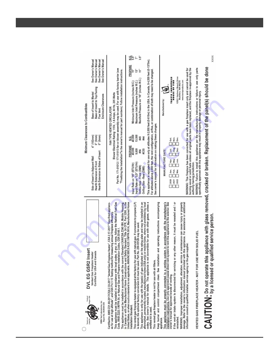
Safety Label
The safety (listing) label is attached to the operating tag (chained to the heater near the gas control valve). A copy is shown below
Page 1: ...DREN TO TOUCH GLASS A barrier designed to reduce the risk of burns from the hot viewing glass is provided with this appliance and shall be installed for the protection of children and other at risk in...
Page 2: ...t and enjoyment from your heater Important Information No other DVL Insert has the same serial number as yours The serial number is attached to the appliance near the gas control valve This serial num...
Page 3: ...stallation 27 Air Shutter Adjustment 28 Before You Begin 29 Remote Control Warnings 29 Location of Controls 30 Remote Set Up 30 Direct Operation 31 Starting the Fireplace for the First Time 32 Intermi...
Page 4: ...lled in Manufactured Housing only after the home is site located All exhaust gases must be vented outside the structure of the living area Combustion air is drawn from outside the living area structur...
Page 5: ...ing and maintenance instructions that you will need at a later time Always follow the instructions in this manual Instruct everyone in the house how to shut the gas off to the appliance and at the gas...
Page 6: ...0 000 Heating capacity will vary with floor plan insulation and outside temperature Dimensions Electrical Specifications Electrical Rating 120 Volts 1 8 Amps 60 Hz 205 watts Fuel This heater is shippe...
Page 7: ...sly The order of installation is not rigid the qualified installer should follow the procedure best suited for the installation Packing List Propane Conversion Kit Orifices Manifold Cover etc Top Conv...
Page 8: ...the large amount of heat this appliance produces when determining a location Fireplace Sizing 1 Piece Panel 1 Piece Panel w Trim Minimum Height 24 7 8 632mm 23 3 4 604mm Minimum Front Width 32 1 2 826...
Page 9: ...rt must be placed directly on the metal base of the metal fireplace CAUTION Firebox floor removal is not covered under the appliance safety standard ANSI Z21 88 CSA 2 33 used in the safety certificati...
Page 10: ...ies 9 17 2020 1536 DVL EG GSR2 Leveling Legs This heater includes front and rear leveling legs to accommodate fireplaces with a step down firebox Loosen the 8 bolts and adjust the legs down until the...
Page 11: ...e side of the insert See the directions below for details Using the Insert Wiring Kit See the instructions included with the Insert wiring kit for attaching the kit to the side of the insert a b c d R...
Page 12: ...non combustible top facing must extend 35 1 2 902mm above the base of the insert or to the bottom of the mantel whichever is less Mantel Clearances The maximum mantel depth is 12 305mm NOTE The combus...
Page 13: ...of 1 2 psig For pressures under 1 2 psig isolate the gas supply piping by closing the manual shutoff valve Leak test all gas line joints and the gas control valve prior to and after starting the heat...
Page 14: ...ing it into chimney offsets When installed the vent must meet all of the vent manufacturer s requirements Use the following vent 4 UL 441 or 1777 Gas Liner for Exhaust 3 UL 441 or 1777 Gas Liner for A...
Page 15: ...he baffle to the top of the firebox Slide the baffle slightly forward until the screw heads are in line with the keyhole slots Lower the baffle and remove from the firebox Re install baffle after the...
Page 16: ...avent com Secure the flex to the insert and termination using screws or hose clamps Vent Location Inlet 3 76mm Exhaust 4 102mm Inlet Exhaust 3 76mm dia 4 102mm dia Inlet Exhaust Additional Coaxial Sec...
Page 17: ...acceptable in your area This type of installation requires a minimum chimney cross section of 48 square inches Factory Built Metal Wood Burning Fireplace Inlet Exhaust Re Line Exhaust Only Re Line Re...
Page 18: ...w for installation Locate the screw in the top center of the front of the insert Use a nut driver to remove the screw and slide the connector toward the back of the insert to disengage the connector f...
Page 19: ...connector to the appliance using the screw removed in step 1 Altitude Considerations This heater has been tested at altitudes ranging from sea level to 6 000 feet 1 800 M In this testing we have foun...
Page 20: ...aVent Part For inserts that use 3 exhaust and 3 intake 46DVA HCL33 For inserts that use 3 exhaust and 4 intake 46DVA HCL34 Refer to the kit manufacturer s instructions for details and requirements for...
Page 21: ...roved for use with Travis Industries gas inserts These kits can be purchased from your DuraVent dealer Application DuraVent Part DuraVent Stock For inserts that use 3 exhaust and 3 intake 46DVA CLTA 8...
Page 22: ...Use of the Extended Position Notch This surround panel has 2 notches Notch position is determined by the face being used see below Standard Position used for all faces except for the arched faces wit...
Page 23: ...r to installing brackets a Remove the two screws from the air deflector b Slide the upper mounting brackets into place NOTE The brackets slide under the air deflector Secure the upper brackets with th...
Page 24: ...n below Ember Glo Only Panel Installation Before installation the insert should be in place with the gas line and vent attached Pull the insert out slightly to assist in the installation 1 Bend all 4...
Page 25: ...ift the glass frame up and pull it forward to remove NOTE You may need to lift the glass frame while re attaching b a 4 A A B a t t e r i e s NOTE Replace the cove covers for those faces using them Gl...
Page 26: ...A visual deflector is included with the insert to help ensure that the controls and valve area are not visible The deflector is held in place by magnets on each end To remove grab the deflector by bot...
Page 27: ...correctly NOTE Take care to not touch the bulb with your fingers use a cloth or paper towel Firebox Ceiling Accent Light 4 Install the four AA batteries see illustration below The AA batteries act as...
Page 28: ...hould not contact the top of the firebox Check the flame on low position The flames should burn off of each burner hole If the heater does not work correctly contact your Travis dealer for a remedy 12...
Page 29: ...e appliance We do not recommend disabling the standing pilot option for our gas appliances This feature may be recommended for cold regions or installations with sub optimal venting How to Disable Ena...
Page 30: ...it see Figure 1 This switch must remain in the REMOTE position for the remote to operate Figure 1 Most features will be controlled by the included remote F Swing the access door down or remove the fa...
Page 31: ...econds The pilot will start to spark repeatedly signifying all system memory has been cleared The system will return to its original configuration a remote will need to be synchronized and the system...
Page 32: ...in very cold conditions you may notice that the burner does not light quickly and the flames lift off the burner If this is the situation we recommend you switch to continuous pilot This will create a...
Page 33: ...eed to reset the pilot mode during the heating season we have listed a few strategies below Option 1 Remember to periodically turn on the heater during the heating season If you use your heater for su...
Page 34: ...sections see Figure 5 Figure 5 Listen for the Beep Each time you press a button on the transmitter that controls the fireplace a beep will come from the IFC When you change thermostat target settings...
Page 35: ...igure 8 STANDARD THERMOSTAT While in standard thermostat setting the transmitter will turn the burner on and off to achieve the target temperature see Figure 9 below To adjust the target temperature p...
Page 36: ...display will display the 7 settings from OFF to HI for full on Figure 12 MANUAL MODE BLOWER OPERATION When in Manual Mode the blower will remain on even if the burner is turned off and the heater coo...
Page 37: ...center display will display either ON or OFF Figure 14 Ember Glo Light AUX The Ember Glo light may be turned on and off using the up and down buttons see illustration below You can adjust the brightn...
Page 38: ...nto the battery box when this occurs see Battery Installation on page 38 In applications where the appliance is required to provide heat we recommend replacing the batteries before each heating season...
Page 39: ...is is normal during start up You may notice the smell is more acute if the appliance was left idle for a long period MAX F OFF Child Proof Indicator Gas Control Valve As the gas control valve is turne...
Page 40: ...prior to turning the heater on Clean the plated surfaces with denatured alcohol and a soft cloth with the heater cool Other cleaners may leave a film that may become etched into the surface Accent Li...
Page 41: ...th your fingers use foam packing or a paper towel to handle the bulbs 35 Watt 120 Volt T4 Halogen Bulb GY6 35 Base Ember Glo Bulb Replacement The Ember Glo lights in your insert provide additional lig...
Page 42: ...out bulb and remove it from the socket by pulling the bulb directly away from socket do not twist 7 Gently insert the pins on the replacement bulb into the holes on the socket NOTE Take care to not t...
Page 43: ...Check the gas control valve and the gas lines If damage is found discontinue use and contact your dealer for service Clean the air channels ducts and blower if applicable Inspect vent and vent termina...
Page 44: ...tery box switch is turned to OFF or ON The thermostat is set too low Turn the battery box switch to REMOTE Check thermostat Blower Does Not Work The fireplace is not getting electricity The fireplace...
Page 45: ...ge Yellow System Jumper Purple Grey Spark Rod Comfort Control Valve Battery Box Manual On Off Accent Light s Blower s 3 Amp Fuse Appliance Ground Green Orange Yellow Green White Blue IPI CPI JUMPER WI...
Page 46: ...or broken Replacement of the glass should be done by a licensed or qualified service person SCREEN BARRIER ARCHED 250 03377 SCREEN BARRIER RECTANGLE 250 03379 PILOT ASS Y 3 WAY PSE 250 02903 VALVE NG...
Page 47: ...afety Label 47 Travis Industries 9 17 2020 1536 DVL EG GSR2 Safety Label The safety listing label is attached to the operating tag chained to the heater near the gas control valve A copy is shown belo...
Page 48: ...while the appliance is in transit alteration or act of God 8 This 7 Year warranty excludes damage caused by normal wear and tear such as paint discoloration or chipping worn or torn gasketing corrode...
Page 49: ...y result causing property damage personal injury or loss of life The qualified service agency is responsible for the proper installation of this kit The installation is not proper and complete until t...
Page 50: ...ove and set aside the stock seal plates shown below 5 Install the LP propane orifices ORIFICE SIZE ID Natural Gas LP Propane Front Burner Orifice 45 DMS 56 DMS Rear Burner Orifice 44 DMS C55 DMS NOTE...
Page 51: ...s the stepper motor shown below The stepper motor adjustable regulator has an installation sheet included with it make sure to follow all of the directions Disconnect the wiring from the stepper motor...
Page 52: ...ammonia free glass cleaner i e vinegar and water to clean the fireback CERAMIC FIREBACK WARNINGS The rear fireback is rectangular and must be placed right side up Lay the firebacks on a flat surface p...
Page 53: ...over toward the center of the insert until the hole in the cover lines up with the head of the screw Lift up slightly and remove the cover from the firebox Repeat for other cover Set the covers aside...
Page 54: ...parate the top glass clips from the bottom glass clips by gently bending the back and forth at the perferations about 1 3 from the end 7 Prepare the side firebacks for installation Each side uses 1 la...
Page 55: ...e next step Support the rear fireback with your hand until at least one side fireback is in place next step 9 Install one of the side panels into the firebox as shown below The side fireback rests on...
Page 56: ...back the fireback will be sandwiched between the clip and the side of the firebox Tighten the screws to lock the glass in place see below 11 Repeat steps 8 and 9 for the opposite side fireback 12 Rein...
Page 57: ...ilure to have all of the accessories available at the time of installation will delay installation and may lead to unnecessary disassembly of components 1 Run gas line to the fireplace 2 Remove the gl...
Page 58: ...view Oak Lg sku 94500952 When installed the ten 10 logs should appear as shown below Front Left Log 250 05179 Center Left Twig 250 05172 Left Twig 250 05175 Center Twig 250 05176 Front Ember Chunk 250...
Page 59: ...iew Birch Lg sku 94500951 When installed the ten 10 logs should appear as shown below Center Log 250 05183 Left Log 250 05187 Center Twig 250 05186 Right Bottom Log 250 05188 Front Left Log 250 05189...
Page 60: ...manual for further details 1 Place the rear log as shown below The two slots on the bottom of the log sit over the pin on the burner With the rear log in place push it all the way back 2 Place the le...
Page 61: ...is in contact with the sloped area between the front and rear burner Make sure burner holes are not obstructed 4 Detail around the burner with ember chunks Cover any exposed metal between the side of...
Page 62: ...he glow from the burner The rockwool can be applied in a relatively thick layer The best method for applying the rock wool is to brush it on to the burner Compress a clump of rockwool between your thu...
Page 63: ...r a realistic glowing ember appearance NOTE If power is supplied to the insert it can helpful to turn the lights on while painting so you can determine an appropriate amount of paint for a realistic e...
Page 64: ...d of the log sits forward of the second vertical finger of the grate There are also two channels on the bottom of the log that rest on the side and front edges of the burner 10 The right top log has t...
Page 65: ...he center twig rests on the tip of the right bottom log and has a notch that rests on the middle vertical finger of the grate 12 The center log rests on a pin on the left end of the rear log and the o...
Page 66: ...for qualified installers only Travis Industries 9 17 2020 1536 DVL EG GSR2 13 Place the right ember chunk as shown below 14 The left twig sets on the left most pin on the front left log and the top r...
Page 67: ...tries 9 17 2020 1536 DVL EG GSR2 15 Place the center left twig over the remaining pin on the front left log The burnt end of the log should rest on or near the grate 16 Place any remaining ember chunk...
Page 68: ...the Face 7 Leveling Legs 10 Location of Controls 30 Low Battery Indicator 38 LP Conversion Instructions 49 Maintaining Your Heater s Appearance 40 Normal Operating Odors 39 Normal Operating Sounds 39...