


4
SISTF10xx-140-LR(T) / -160-LR(T) / -170-LR(T)
24-hour Technical Support:
1-800-260-1312
-- International:
00-1-952-941-7600
NOTE:
The Ethernet switch is intended to be grounded to a well-
grounded mounting surface such as a metal plate. Install the grounding
wire prior to connecting any other device.
Ground the Ethernet Switch
Grounding the Ethernet switch helps limit the effects of noise due to
electromagnetic interference (EMI). The grounding screw is located on the top
panel next to the terminal block.
To ground the device:
1.
Connect one end of the grounding wire (not included) to the grounding
screw by looping one end of the grounding wire under the star washer.
2.
Tighten the grounding screw with a phillips-head screwdriver.
3.
Connect the other end of the grounding wire to earth ground.
grounding screw
terminal block
DIN-Rail
spring
mounting
plate
Step 1:
Step 2:
Installation
DIN-Rail Mount
The Ethernet switch includes an aluminum DIN-Rail mounting plate attached
to the device’s back panel. To mount the device onto a DIN-Rail:
1.
Insert the top of the DIN-Rail into the upper slot of the mounting plate.
The stiff metal spring should be positioned behind the DIN-Rail.
2.
Push down and rotate the device to snap it into place on the DIN-Rail as
shown.
-- Click the
“Transition Now”
link for a live Web chat.
5
Installation
-- Continued
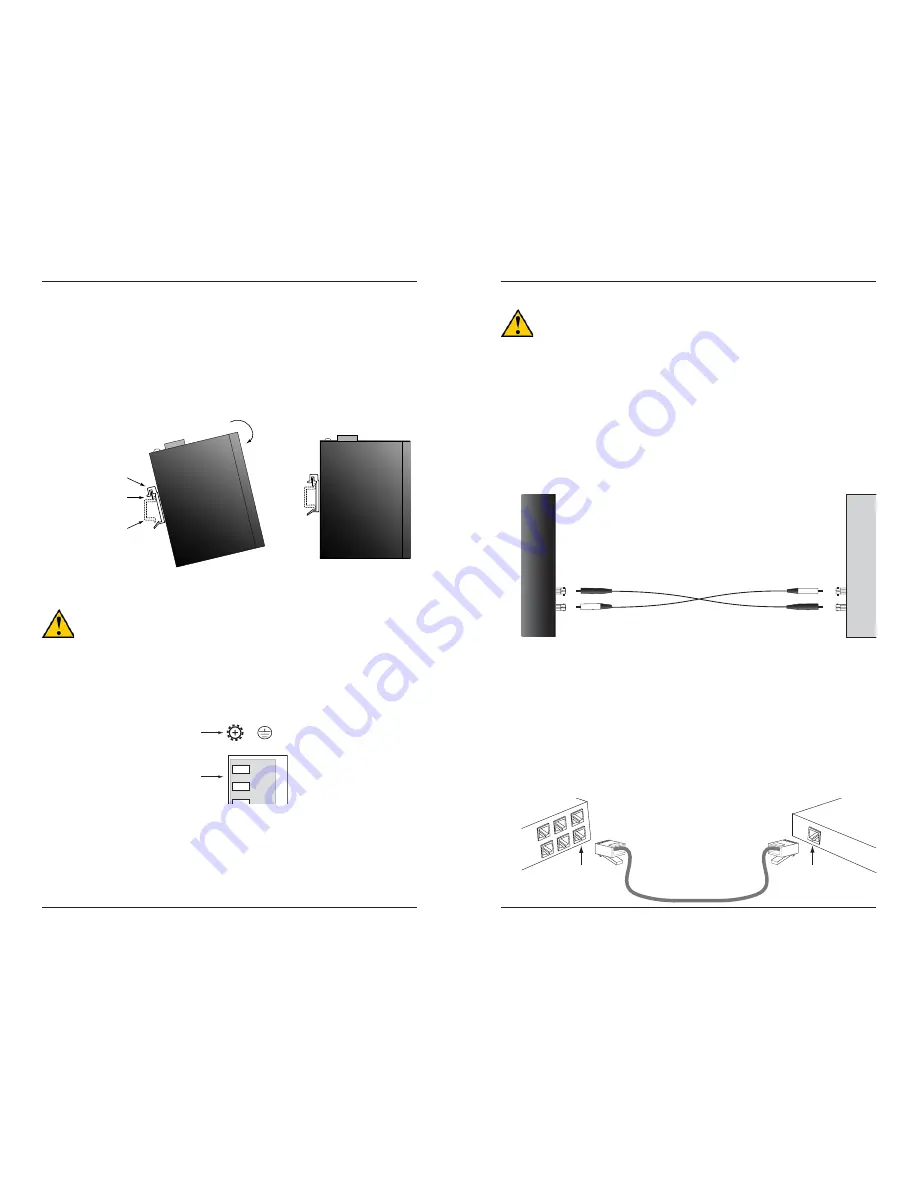
CAUTION:
Disconnect the Ethernet switch from the DC power source
BEFORE installing and/or wiring the device.
Install the Fiber Cable
1.
Locate or build 100Base-FX fiber cable with male, two-stranded TX to RX
connectors installed at both ends.
2.
Connect the fiber cables to the Ethernet switch as described:
• Connect the male
TX
cable connector to the female
TX
port.
• Connect the male
RX
cable connector to the female
RX
port.
3.
Connect the fiber cables to the other device (another media converter,
hub, etc.) as described:
• Connect the male
TX
cable connector to the female
RX
port.
• Connect the male
RX
cable connector to the female
TX
port.
Connect the
fiber cable to the
Ethernet switch
as shown.
Connect the fiber cable
to the other device
(media converter,
switch, etc.) as shown
RX
TX
RX
TX
Install the Copper Cable
The AutoCross feature allows either straight-through (MDI) or crossover (MDI-
X) copper cable to be used when connecting devices via the RJ-45 port.
1.
Locate or build 10Base-T or 100Base-TX copper cables with male, RJ-45
connectors installed at both ends.
2.
Connect the RJ-45 connector at one end of the cable to the RJ-45 port on
the Ethernet switch.
3.
Connect the RJ-45 connector at the other end of the cable to the RJ-45
port on the other device (PLC, workstation, etc.).
RJ-45 port
on the other device
(PLC, work station, etc.)
RJ-45 ports on the
Ethernet switch


