


Transition Networks
E-TBT-MC05 10Base-T Transceiver User Guide
33406 Rev. C
Page
10
of
14
Technical Specifications
For use with Transition Networks’ Model E
-TBT-MC05 or equivalent.
Standards
IEEE 802.3ab, IEEE 802.3
Data Rate
10 Mbps
Dimensions
1.77" x 0.81” x 3.14" (44.96 mm x 20.57mm x 79.76mm)
Weight
0.2 lbs. (90.72 g) approximately
Power Consumption Not to exceed 75 mA @ 12VDC
Power Source
AUI port, 500 mA @ 12VDC
Operating Temp
0 to 50°C (32°F to 122°F )
Storage Temp:
-25°C to +85°C (-13°F to +185°F)
Humidity:
5 to 95%, non-condensing
Altitude:
0 to 10,000 feet
MTBF:
125,126 Bellcore hours. Calculated at 40C with a 10C temperature rise.
Warranty
Lifetime
Note
: The information in this user guide is subject to change. For current information on the E-TBT-MC05
Transceiver, view the online user guide at:
IMPORTANT Copper based media ports: e.g., Twisted Pair (TP) Ethernet, USB, RS232, RS422, RS485, DS1, DS3,
Video Coax, etc. are intended connecting to intrabuilding (inside plant) link segments, not subject to lightening
transients or power faults. Copper based media ports: e.g., Twisted Pair (TP) Ethernet, USB, RS232, RS422,
RS485, DS1, DS3, Video Coax, etc. are NOT for connecting inter-building (outside plant) link segments that are
subject to lightening transients or power faults. Failure to observe this notice could result in damage to
equipment.
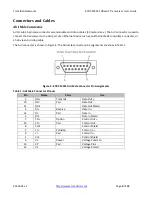
Cable Specifications
The physical characteristics of the media cable must meet or exceed IEEE 802.3 specifications.
Copper Cables
Category 3: (
minimum
requirement
)
Gauge 24 to 22 AWG
Attenuation 11.5 dB/100m @ 5-10 MHz
Maximum cable distance: 100 m
Category 5: (
recommended
)
Gauge 24 to 22 AWG
Attenuation 22.0 dB/100m @ 100 MHz
Maximum cable distance: 100 m
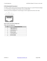
• Straight
-through or crossover twisted-pair cable may be used.
• Shielded (STP) or unshielded (UTP) twisted
-pair cable may be used.
• Pins 1&2 and 3&6 are the two active pairs in an Ethernet
network .
• RJ
-45 Pin-out: Pin 1 = TD+, Pin 2 = TD-, Pin 3 = RD+, Pin 6 = RD-


