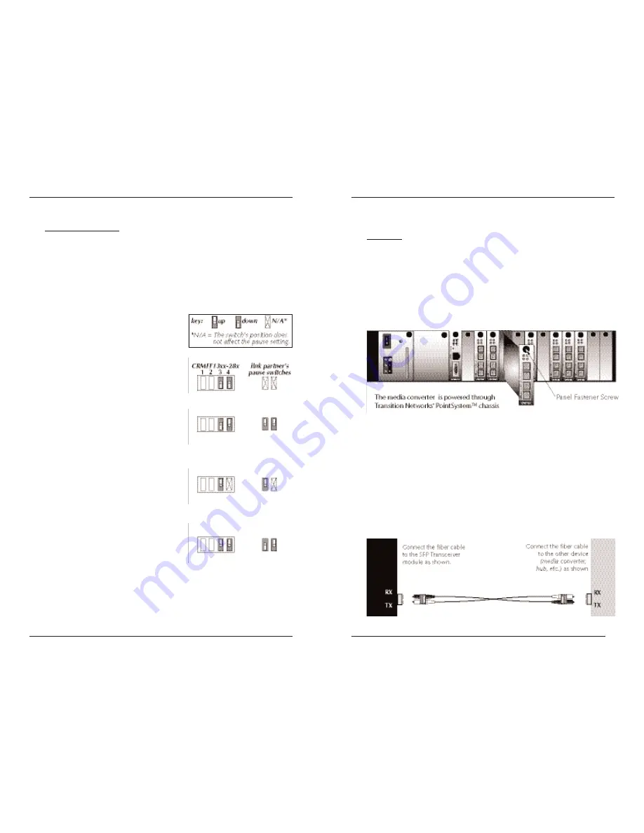
background image

No Pause:

Pause feature is disabled. 

Transmit Only:  

CFMFF13xx-28x can transmit and the
link partner can receive the pause
signal.

Transmit and Receive:   

Both the CFMFF13xx-28x and the
link partner can send and receive the
pause signal. 

Receive Only:

The CFMFF13xx-28x can receive and
the link partner can transmit the
pause signal. 

Installation 

-- Continued

Pause

 (Switches 3 & 4)

The pause feature can improve network performance by allowing one end of
the link to signal the other to discontinue frame transmission for a set period
of time to relieve buffer congestion.

To properly set the pause feature in the network, the link partner

(i.e., the

device to which the CFMFF13xx-28x is linked)

must also have comparable

pause switches.  If the link partner does not have the pause feature, disable
the pause feature on the CFMFF13xx-28x media converter.

The CFMFF13xx-28x has four pause
options 

(listed below)

.  To the right of

each option, a drawing shows the switch
settings for the CFMFF13xx-28x and the
link partner. 

4

CFMFF13xx-28x

24-hour Technical Support: 1-800-260-1312 -- International: 00-1-952-941-7600  

5

[email protected] -- Click the “Transition Now” link for a live Web chat.

Install the Fiber Cable

1.

Locate or build IEEE 802.3™ compliant fiber cable with male, two-
stranded TX to RX connectors installed at both ends.

2.

Connect the fiber cables to the CFMFF13xx-28x media converter as
described: 

Connect the male TX cable connector to the female TX port.

Connect the male RX cable connector to the female RX port.

3.

Connect the fiber cables to the other device 

(another media converter,

hub, etc.) 

as described: 

Connect the male TX cable connector to the female RX port.

Connect the male RX cable connector to the female TX port.

Installation 

-- Continued

Install the CFMFF13xx-28x Slide-in-Module 

CAUTION: Slots in the PointSystem™ chassis without a slide-in-module
installed MUST have a protective plate covering the empty slot for Class A
and/or Class B compliance. 

The media converter slide-in-modules may be installed in any slot, in any
order.  To install the CFMFF13xx-28x slide-in-module:

1.

Carefully slide the slide-in-module into the installation slot, aligning the
module’s circuit board with the installation guides.

2.

Ensure that the module is firmly seated inside the chassis.

3.

Push in and rotate the attached panel fastener screw clockwise to secure
the module to the chassis front. 

Summary of Contents for CFMFF1314-280

Page 1: ...ke most gigabit Ethernet media converters which allow only two media converters in series the CFMFF13xx 28x has a retiming reshaping feature that makes it possible to connect any number of media converters in series Part Number Port One Duplex Fiber Optic 1000Base SX Port Two Duplex Fiber Optic 1000Base LX CFMFF1314 280 SC 850 nm multimode 220 m 721 ft SC 1310 nm single mode 10 km 6 2 miles CFMFF1...

Page 2: ...he jumper is located on the circuit board Use small needle nose pliers to set the recessed switches Hardware The media converter mode is determined by the 4 position switch settings see page 4 Software The media converter mode is determined by the most recently saved on board microprocessor settings See SNMP on page 6 CFMFF1414 280 SC 1310 nm single mode 10 km 6 2 miles SC 1310 nm single mode 10 k...

Page 3: ...00 5 techsupport transition com Click the Transition Now link for a live Web chat Install the Fiber Cable 1 Locate or build IEEE 802 3 compliant fiber cable with male two stranded TX to RX connectors installed at both ends 2 Connect the fiber cables to the CFMFF13xx 28x media converter as described Connect the male TX cable connector to the female TX port Connect the male RX cable connector to the...

Page 4: ...vity min 17 0 dBm max 0 0 dBm Link Budget 7 0 dB Port 2 CFMFF1314 280 1310 nm single mode Fiber optic Transmitter Power min 13 0 dBm max 3 0 dBm Fiber optic Receiver Sensitivity min 20 0 dBm max 3 0 dBm Link Budget 7 0 dB CFMFF1315 280 1310 nm single mode Fiber optic Transmitter Power min 5 0 dBm max 0 0 dBm Fiber optic Receiver Sensitivity min 20 0 dBm max 3 0 dBm Link Budget 15 0 dB CFMFF1317 28...

Page 5: ...x 3 0 dBm Link Budget 27 0 db CFMFF1414 280 Port 2 1310 nm single mode Fiber optic Transmitter Power min 13 0 dBm max 3 0 dBm Fiber optic Receiver Sensitivity min 20 0 dBm max 3 0 dBm Link Budget 7 0 dB 9 techsupport transition com Click the Transition Now link for a live Web chat Troubleshooting If the media converter fails isolate and correct the fault by determining the answers to the following...

Page 6: ...tion Now link Web Based Seminars Transition Networks provides seminars via live web based training Log onto www transition com and click the Learning Center link E Mail Ask a question anytime by sending an e mail to our technical support staff techsupport transition com Address Transition Networks 6475 City West Parkway Minneapolis MN 55344 U S A telephone 952 941 7600 toll free 800 526 9267 fax 9...

Page 7: ... limits for radio noise for digital apparatus set out on the radio interference regulations of the Canadian Department of Communications Le présent appareil numérique n émet pas de bruits radioélectriques dépassant les limites applicables aux appareils numériques de la Class A prescrites dans le Règlement sur le brouillage radioélectrique édicté par le ministère des Communications du Canada Europe...

Reviews: