CFETF10xx-105
2
24-Hour Technical Support:
1-800-260-1312
-- International:
00-1-952-941-7600
Installation
CAUTION:
Wear a grounding device and observe electrostatic discharge
precautions when setting the 4-position switch and the jumper and when
installing the slide-in-module media converter.
Failure to observe this caution
could result in damage to, and subsequent failure of, the media converter.
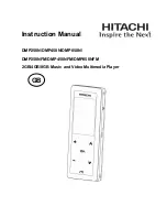
Set the 4-Position Switch
•
The 4-position switch is located
on the circuit board.
•
Use a small flat-blade screwdriver
or a similar device to set the
recessed switches (see the
drawing to the right).
1.
Auto-Negotiation™
up
Advertises 100 Mb/s full-duplex and half-duplex (only during
Auto-Negotiation). (See page 5.)
down
Disable Auto-Negotiation.
2.
Link Pass-Through
up
Enable Link Pass-Through. (See page 6.)
down
Disable Link Pass-Through.
3.
AutoCross™
up
Enable AutoCross™ - The media converter connects automatically
to either straight-through or crossover twisted-pair copper cable.
(See page 5.)
down
Disable AutoCross™ - Either straight-through or crossover twisted-
pair copper cable must be installed, according to the site
requirements.
4.
(not used)
Set the Hardware/Software Jumper
The hardware/software jumper is located on the media converter circuit
board. Use small needle-nosed pliers or a similar device to set the jumper.
Refer to the drawings below when setting the media converter for hardware or
software mode.
Hardware
The media converter mode is determined by
the 4-position switch settings listed above.
Software
The media converter mode is determined by
the most-recently saved, on-board
microprocessor settings.
Software Mode
Hardware Mode
H
S
H
S
Not Used
Link Pass-Through (up=Enable)
AutoCross (up=Enable)
Auto-Negotiation (up=Enable)
1 2 3 4
-- Click the
“Transition Now”
link for a live Web chat.
3
Installation
-- Continued
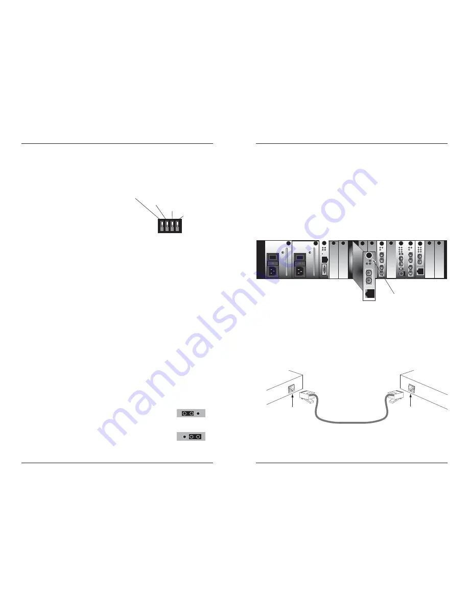
Install the Slide-In-Module
CAUTION:
Wear a grounding device and observe electrostatic discharge
precautions when installing the CFETF10xx-105 slide-in-module media
converter.
Failure to observe this caution could result in damage to, and
subsequent failure of, the media converter.
1.
Carefully slide the slide-in-module into the installation slot, aligning the
module with the installation guides.
2.
Ensure that the module is firmly seated inside the chassis.
3.
Push in and rotate the attached panel fastener screw clockwise to secure
the module to the chassis front.
Connect the Twisted-Pair Copper Cable
1.
Locate or build 100Base-TX compliant cables, with male RJ-45
connectors installed at both ends.
2.
Connect the RJ-45 connector at one end of the cable to the RJ-45 port on
the CFETF10xx-105 media converter.
3.
Connect the RJ-45 connector at the other end of the cable to the RJ-45
port on the other device (switch, workstation, etc.).
CFMFF100
CFMFF100
CETCF100
CFETF100
CFETF110
CFMFF100
SPD
PWR
FRX
CRX
FLNK
CLNK
10/100TX
RX
TX
10/100SX
100BASE-TX
RX
TX
100BASE-FX
Link Alert
E
D
0
50½
LA
PWR
RXF
RXC
LNK
COL
LKS
PWR
LKM
10BASE-2
10BASE-FL
LKS
PWR
LKM
LKS
PWR
LKM
Multimode
Singlemode
TX
RX
TX
RX
Multimode
Singlemode
TX
RX
TX
RX
Multimode
Singlemode
TX
RX
TX
RX
I
0
TERM
INIT
RX
TX
LNK
PWR
CPSMM120
SERIAL
10BASE-T
R
E
S
E
T
I
0
PWR
TX
FX
100BASE-TX
RX
TX
100BASE-FX
panel fastener screw
RJ-45 port
on the other device
(switch, work station, etc.)
RJ-45 port
on the media
converter