INSTALLATION
(continued)
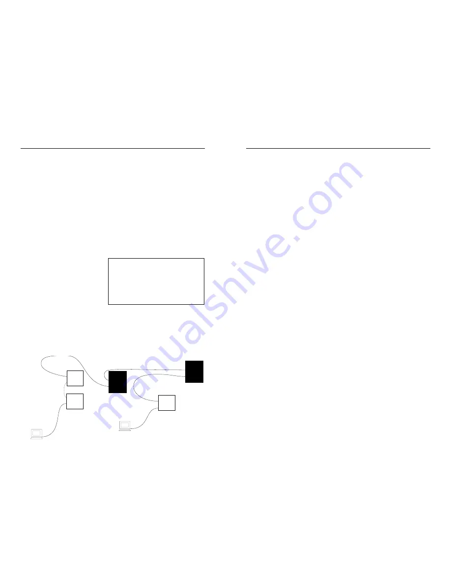
Using the 512-Bit Rule (100BASE-TX/100BASE-FX)
A bit-time (BT) is the amount of time required to send one data bit
across an Ethernet LAN. The total number of bit-times between any
two DTEs in the same Fast Ethernet 100BASE-TX or 100BASE-FX
collision domain cannot exceed 512 bit-times in the round trip.
To calculate the round trip delay in bit-times between a station (DTE)
and the Transition Networks’ bridging media converter, determine the
Fast Ethernet worst case round-trip delays expressed in bit times:
•
Find the longest and most complicated collision domain path
between the station and the Transition Networks’ Bridging Media
Converter.
•
Calculate the round trip delay for each cable segment by
multiplying the length of
the cable (in meters) by
the delay per meter (in bit
times (BT)) for each cable
type as listed in the table
•
Calculate the total round
trip delay by taking the
sum of all the individual cable delay values in the path, as listed in
the table, plus station (DTE) delays and hub (repeater) delays.
•
Add the segment delay values together. If the result is less than or
equal to 512 bit times, the path passes the test.
NOTE: Actual manufacturers’ bit-time values and/or measured bit-time
values may be greater or less than bit-time values listed in the chart.
Connecting Copper Cable (10BASE-T/100BASE-TX)
Ensure that the correct cable type is installed to support the highest
speed and mode of operation to be selected. Though Category 3 cable
is adequate for the 10BASE-T installation, Category 5 cable is strongly
recommended, since Category 3 cable can NOT be used for
100BASE-TX.
10BASE-T AND THE ETHERNET COLLISION DOMAIN
•
Refer to the 5-Segment Rule (page 8) before installing half-duplex
10BASE-T cable.
•
Installing full-duplex twisted-pair cable avoids collision domain
considerations; distances remain
≤
100 meters.
100BASE-TX AND THE FAST ETHERNET COLLISION DOMAIN
•
Refer to the 512-Bit Rule before installing half-duplex 100BASE-
TX cable.
•
Installing full-duplex twisted-pair cable avoids collision domain
considerations; distances remain
≤
100 meters.
•
NOTE: A Fast Ethernet collision domain can have ONLY ONE
CLASS I repeater OR TWO CLASS II repeaters.
INSTALLING CABLE
To install 10BASE-T or 100BASE-TX cable:
1. Locate or build 10BASE-T or 100BASE-TX cables:
•
803.2 (10BASE-T) or 803.2u (100BASE-TX) compliant
•
with Straight-through or Crossover RJ-45 cable/connectors as
required for site installation (page 13)
•
with RJ-45 plug connectors installed at both cable ends.
2. Connect RJ-45 plug connector at one end of 10BASE-T or
100BASE-TX cable to bridging media converter RJ-45 jack
connector.
3. Connect RJ-45 plug connector at other end of 10BASE-T or
100BASE-TX cable to RJ-45 jack connector on network device.
.
Full-Duplex Fiber/NO Collision Domain
Collision Domain
Class II
Hub
Collision Domain
Class I
Hub
100 meters TP
@ 1.11BT/meter
= 111BT
5 meters TP
@ 1.11BT/meter
= 5.55BT
DTE= 50BT
= 140BT
= 92BT
Class II
Hub
= 92BT
Switch
= 50BT
100 meters TP
@ 1.11BT/meter
= 111BT
100 meters TP
@ 1.11BT/meter
= 111BT
100 meters TP
@ 1.11BT/meter
= 111BT
Switch
= 50BT
DTE= 50BT
50.00BT
+111.00BT
+92.00BT
+5.55BT
+92.00BT
+111.00BT
50.00BT
___________
= 511.55BT
50.00BT
+111.00BT
+140.00BT
+111.00BT
50.00BT
___________
= 462.00BT
Class I Repeater . . . . . . . . . . . . . . . . .140 BT
Class II Repeater . . . . . . . . . . . . . . . . . .92 BT
Class I TX/FX Media Converter . . . . . .130 BT
Class II TX/FX Media Converter . . . . . .92 BT
DTE . . . . . . . . . . . . . . . . . . . . . . . . . . .50 BT
1 meter of CAT.5 TP cable . . . . . . . . .1.11 BT
1 meter of fiber cable . . . . . . . . . . . . . . .1 BT
Bridging Media Converter . . . . . . . . . . .50 BT
Summary of Contents for C/E-PSW-FX-03
Page 9: ......


