LCA
LOAD CELL AMPLIFIER
SIGNAL CONDITIONER
Modules LCA-9PC & LCA-RTC
OPERATOR MANUAL
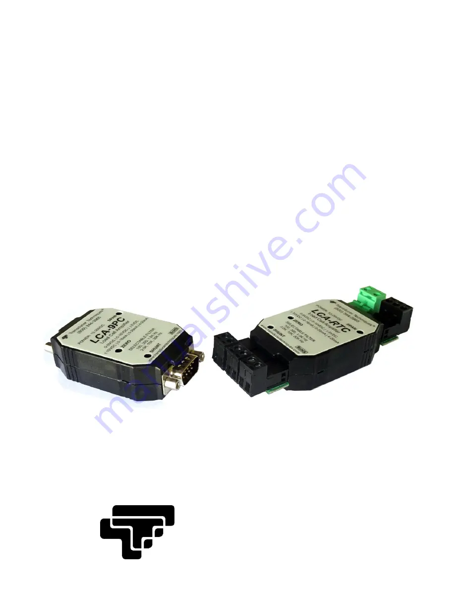
Model LCA-9PC
(DB9 connectors)
Model LCA-RTC
(removable terminal connectors)
Transducer
Techniques
®
Page 1: ...LCA LOAD CELL AMPLIFIER SIGNAL CONDITIONER Modules LCA 9PC LCA RTC OPERATOR MANUAL Model LCA 9PC DB9 connectors Model LCA RTC removable terminal connectors Transducer Techniques...
Page 2: ...ONS 3 SETUP USING JUMPERS POTENTIOMETERS 4 ELECTRICAL CONNECTIONS 7 CALIBRATION 10 OPERATING RECOMMENDATIONS 12 SPECIFICATIONS 13 CASE DIMENSIONS 15 TROUBLESHOOTING 15 CIRCUIT BOARD DIMENSIONS 16 ACCE...
Page 3: ...hen the unit provides 10V DC excitation to a 350 ohm load cell while delivering a 20 mA analog output MOUNTING PROVISIONS 1 DIN Rail Mounting of Cased LCA Units can be via the 35 mm DIN Rail Mounting...
Page 4: ...oard which are high lighted in gray in Figure 2 and are labeled E1 thru E8 After resetting jumpers and with the case still open apply signal and power and use a multimeter to measure the signal output...
Page 5: ...5V or 10V load cell sensi tivity 0 5 to 10 0 mV V and signal output 0 5V 0 10V 0 16 mA 0 20 mA or 4 20 mA Exc Output Load cell sensitivity in mV V Vo Io 0 5 1 0 1 5 2 0 2 5 3 0 4 0 10 0 5V 1 5V 4 20...
Page 6: ...nt calibration resistor Do not set the E7 jumper for use of a user furnished custom shunt calibration resistor Calibration Resistor Standard Custom E7 jumper install none Factory default setting A cus...
Page 7: ...was implemented in July 2017 for the LCA RTC to change the green power connector from 3 pins to 2 pins and to increase the pitch or spacing between the power connecter pins In combination these two ch...
Page 8: ...input Pin 1 Io Current output Pin 2 GND Electrical ground Pin 3 Vo Voltage output Pin 4 GND Electrical ground Pin 5 Vpwr Power input 11 8 26V Pin 6 GND Electrical ground Pin 7 GND Electrical ground P...
Page 9: ...sed with Revision G or later units To determine the LCA 9PC revision Revisions G and later J1 Male Requires female DB9 cable connector to sensor J2 Female Requires male DB9 cable connector to input po...
Page 10: ...up to achieve maximum stability and accuracy 7 With zero load applied to the transducer adjust the zero potentiometer to obtain a zero reading on the voltmeter 8 Refer to the sample calibration certif...
Page 11: ...11 The Cert below is an example only Please use the Cert supplied with your sensor when calibrating your LCA unit Figure 4 Typical Certificate of Calibration Cert...
Page 12: ...mize changing air flows around the LCA unit Allow the LCA to warm up before taking measurements Allow 15 minutes if the LCA does not provide sensor excitation is powered by 12V and a voltage output is...
Page 13: ...selectable Voltage Load 5 k min Span Range 50 to 4000 Noise and Ripple See chart on page 14 Current Source 0 16 mA 0 20 mA or 4 20 mA jumper selectable Current Load 0 500 10V compliance Nonlinearity...
Page 14: ...m L x W x H Dimensions with DB9 3 1 x 1 7 x 0 8 78 x 43 x 20 mm L x W x H For length make allowance for user furnished DB9 mating connectors Dimensions with Plugs 3 5 x 1 7 x 0 8 90 x 43 x 20 mm L x W...
Page 15: ...gnal wire positions on J1 connector or move the two jumpers on header E1 from positions a a to b b Analog output is saturated Recheck jumper positions on header E2 to ensure that proper voltage gain h...
Page 16: ...16 CIRCUIT BOARD DIMENSIONS inches LCA RTC Board Dimensions LCA 9PC Board Dimensions...
Page 17: ...rail clip open the clamshell case and lift out the circuit board from the case bottom Place the case bottom over the DIN rail clip align the four sets of holes and push in the provided four plastic r...
Page 18: ...part number 2 a serial number for the defective product 3 a technical description of the defect 4 a no charge purchase order num ber so products can be returned to you correctly and 5 ship to and bill...