background image

Federal Communication Commission Interference Statement 


This device complies with Part 15 of the FCC Rules. Operation is subject to 

the following two conditions: (1) This device may not cause harmful 

interference, and (2) this device must accept any interference received, 

including interference that may cause undesired operation. 


This equipment has been tested and found to comply with the limits for a 

Class B digital device, pursuant to Part 15 of the FCC Rules.    These limits 

are designed to provide reasonable protection against harmful interference in a 

residential installation. This equipment generates, uses and can radiate radio 

frequency energy and, if not installed and used in accordance with the 

instructions, may cause harmful interference to radio communications.  

However, there is no guarantee that interference will not occur in a particular 

installation.  If this equipment does cause harmful interference to radio or 

television reception, which can be determined by turning the equipment off 

and on, the user is encouraged to try to correct the interference by one of the 

following measures: 


-  Reorient or relocate the receiving antenna. 

-  Increase the separation between the equipment and receiver. 

-  Connect the equipment into an outlet on a circuit different from that 

to which the receiver is connected. 

-  Consult the dealer or an experienced radio/TV technician for help. 


FCC Caution: Any changes or modifications not expressly approved by the 

party responsible for compliance could void the user's authority to operate this 

equipment. 


This transmitter must not be co-located or operating in conjunction with any 

other antenna or transmitter. 


FOR MOBILE DEVICE USAGE (>20cm/low power) 


Radiation Exposure Statement:


This equipment complies with FCC radiation exposure limits set forth for an 

uncontrolled environment. This equipment should be installed and operated 

with minimum distance 20cm between the radiator & your body. 

Summary of Contents for DAS-2420

Page 1: ...stal clear audio Feature z 2 4GHz ISM band z ID Pairing z 34 channels Frequency hopping z 1 1 1 N Application z Portable receiver with batteries powering and DC adaptor powering z Frequency hopping to...

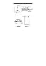
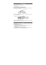
Page 2: ...Connectors and control 2 Power Switch Audio Pairing Switch DC Power input Volume LED Lamp Power Switch LED Lamp Volume DC Power Audio Pairing Switch Receiver Transmitter...

Page 3: ...nd on the user is encouraged to try to correct the interference by one of the following measures z Reorient or relocate the receiving antenna z Increase the separation between the equipment and receiv...

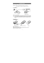
Page 4: ...to the 3 5mm socket on the Tx unit another RL connector to the Speaker out or line out of your TV set Step3 Take out the AC DC adaptor plug the barrel end to the DC socket of DAS 2420 the AC blade en...

Page 5: ...he DC socket of RX Step4 Connect the AC blade end to your AC outlet please be noticed DO NOT OVERLOAD YOUR AC Outlet Note When you using AC DC Adaptor the power from batteries is cut Strap for hanging...

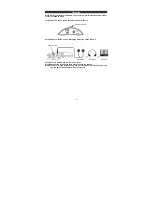
Page 6: ...he Tx Step2 Power on the Rx unit via sliding the Power key on the RX unit Step4 Turn the Volume of Rx to the lowest value Step5 Connect the earphone to the Audio socket on the RX unit Step6 You have f...

Page 7: ...iring mode The LED on Rx will be blinking Step5 When the pairing procedure is ok LED on Tx and Rx will dimmed at the same time Pairing is OK It will take 10 sec to do the pairing FAQ No audio output 1...

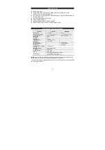
Page 8: ...y range 2406 2472 MHz 2406 2472 MHz Modulation GFSK Channels 34 TX Power 15 dBm Input impedance 10K Ohm 3 5mm Input level 2Vp p Max RX Sensitivity 78 dBm Min Output impedance 16 Ohm Nominal Output lev...

Page 9: ...on If this equipment does cause harmful interference to radio or television reception which can be determined by turning the equipment off and on the user is encouraged to try to correct the interfere...

Reviews: