background image

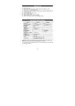
SAFETY NOTICE 


z

  INDOOR USE ONLY. 

z

  THIS DEVICE WITH WIRELESS RF SIGNAL RECEPTION,CONSULT YOUR 

DOCTOR IF YOU WEAR PACEMAKER. 

z

  IF YOU GO OUT FOR MORE THAN 2 WEEKS, PLEASE TAKE THE BATTERIES OUT 

FROM YOUR RX UNIT. 

z

  CLEAN WITH DRY AND SOFT CLOTH. 

z

  DO NOT OPEN THE UNIT.   

z

  NO SERVICEABLE PARTS FOR CUSTOMER. 

z

  DO NOT USE THIS UNIT IN THE HOT AND DAMP PLACE. 


Digital Audio Sender Specifications 


Model NO.


Transmitter 


RECEIVER


Description 

 Transmitter 

  Receiver 


Operating temperature 


0 ~ +60 (degrees Celsius) 

0 ~ +60 (degrees Celsius) 

Frequency range 


2406 ~ 2472 MHz   

2406 ~ 2472 MHz 

Modulation 

 GFSK 


Channels 

 34 

TX Power 

 15 

dBm 


Input impedance 


>10K Ohm (3.5mm) 


Input level 

 2Vp-p 

(Max) 


RX Sensitivity 


-78 dBm (Min.)   

Output impedance   


16 Ohm (

Nominal

Output level 


2Vp-p 

(Max) 

Transmit Distance Between 
Tx & Rx 

100ft(Min, LOS) 

Response (station)


20 ~ 20 KHz, ±0.5dB   

Crosstalk 

-70dB  (Min) 

S/N ratio (station)


70dB  (Min) 

THD + N 


5%  (Max) 

Power supply 

AC 90~240V@50/60Hz/DC 5V, 1000mA 
PLUG: 5.5mmx2.1mmx11mm 
Polarity: Outside Jack(-) Inside Jack(+) 


NOTE:

 The changes or modifications not expressly approved by the party responsible for 

compliance could void the user’s authority to operate the equipment. 
 
To avoid the interference, please far away the sources of interference such as wireless LAN 
AP, Microwave OVEN etc 


Summary of Contents for DAS-2420

Page 1: ...stal clear audio Feature z 2 4GHz ISM band z ID Pairing z 34 channels Frequency hopping z 1 1 1 N Application z Portable receiver with batteries powering and DC adaptor powering z Frequency hopping to...

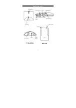
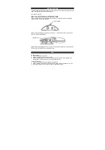
Page 2: ...Connectors and control 2 Power Switch Audio Pairing Switch DC Power input Volume LED Lamp Power Switch LED Lamp Volume DC Power Audio Pairing Switch Receiver Transmitter...

Page 3: ...nd on the user is encouraged to try to correct the interference by one of the following measures z Reorient or relocate the receiving antenna z Increase the separation between the equipment and receiv...

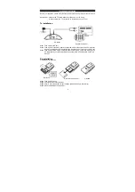
Page 4: ...to the 3 5mm socket on the Tx unit another RL connector to the Speaker out or line out of your TV set Step3 Take out the AC DC adaptor plug the barrel end to the DC socket of DAS 2420 the AC blade en...

Page 5: ...he DC socket of RX Step4 Connect the AC blade end to your AC outlet please be noticed DO NOT OVERLOAD YOUR AC Outlet Note When you using AC DC Adaptor the power from batteries is cut Strap for hanging...

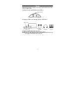
Page 6: ...he Tx Step2 Power on the Rx unit via sliding the Power key on the RX unit Step4 Turn the Volume of Rx to the lowest value Step5 Connect the earphone to the Audio socket on the RX unit Step6 You have f...

Page 7: ...iring mode The LED on Rx will be blinking Step5 When the pairing procedure is ok LED on Tx and Rx will dimmed at the same time Pairing is OK It will take 10 sec to do the pairing FAQ No audio output 1...

Page 8: ...y range 2406 2472 MHz 2406 2472 MHz Modulation GFSK Channels 34 TX Power 15 dBm Input impedance 10K Ohm 3 5mm Input level 2Vp p Max RX Sensitivity 78 dBm Min Output impedance 16 Ohm Nominal Output lev...

Page 9: ...on If this equipment does cause harmful interference to radio or television reception which can be determined by turning the equipment off and on the user is encouraged to try to correct the interfere...

Reviews: