42
•
Blockage of burner tubes or orifi ces
•
Blockage of blower inlet
•
Low voltage supply causing blower to “spin” slower
•
Improper heater location installation
•
Incorrect gas supply pipe size
•
Excessive water fl ow through heat exchanger
•
LP tank below 30% full
COMBUSTION CHAMBER:
The combustion chamber is a single-piece casting. If damaged, the entire chamber must be replaced.
BURNER INSPECTION AND CLEANING:
With the heater “ON”, remove the front access panel and make a visual inspection of the main burners
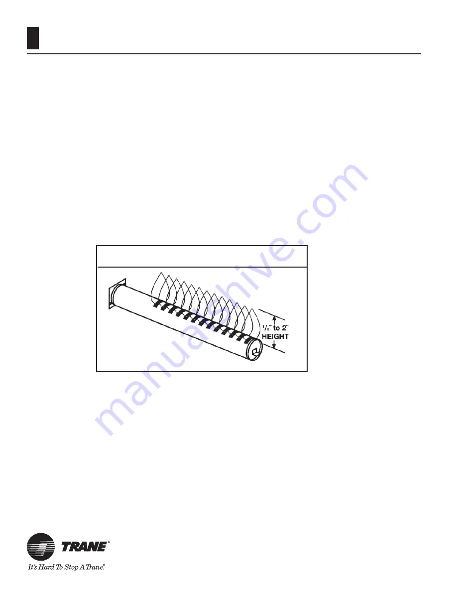
through the sight glass (see Figure 21.) The main burner fl ames should be about ½” to 2” in height and should
not “lift” off the burner ports (see Figure 25).
A normal fl ame is blue, without yellow tips. Yellow tips or a totally yellow or “lazy” fl ame may be an indi-
cation of a fuel-rich mixture due to restricted air supply. Spider nests in the burner and/or gas orifi ces may also
cause yellow tips.
BURNER REMOVAL AND REPLACEMENT:
Refer to Figure 8, Figure 21, and Figure 22 as needed.
1.
Turn pump, gas supply, and heater power “OFF”.
2.
Turn gas valve knob “OFF”.
3.
Remove the front access panel.
4.
Disconnect the union joint in the gas supply piping outside the heater cabinet.
5.
Disconnect the wiring terminals from the gas valve.
6.
Disconnect the wiring terminals from the blower.
7.
Remove the gas manifold assembly. It is attached
to the air box using (4) screws.
8.
Remove the screws from the igniter access panel and pull it out of the way. Do not disconnect the
wires.
9.
Remove the air box cover. Do not remove the blower from the air box cover.
10.
Remove the (2) screws securing each burner to the combustion chamber front.
Figure 25: Burner Flame characteristics


