SS-SVX07B-E4
15
Installation
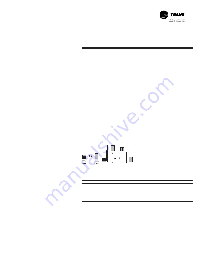
Table 10 - Recommended piping R407C/R22
D3
D2
D1
Line diameter (inches)
Outdoor unit
Indoor unit
(m)
(m)
(m)
Gas
Liquid
TTK/TWK 512
MCD/MWD 512
20
12
15
1/2
1/4
TTK/TWK 518
MCD/MWD 518
24
18
24
5/8
3/8
TTK/TWK 524
MCD/MWD 524
24
18
24
5/8
3/8
TTK/TWK 530
MCD/MWD 530
12
12
12
5/8
3/8
40
18
24
7/8
TTK/TWK 536
MCD/MWD 536
18
18
18
3/4
3/8
40
24
7/8
TTK/TWK 048
MCD/MWD 048
24
18
24
7/8
3/8
40
1 1/8
TTK/TWK 060
MCD/MWD 060
18
12
18
7/8
3/8
40
18
24
1 1/8
1/2
Choice of installation
position
To ensure correct installation, the
following points must be
considered.
- The ceiling must be strong enough
to support the weight of the unit.
- Choose a place where it will be
easy to comply with the
recommended clearances, taking
into account the additional space
required due to external
accessories.
- Take into consideration the drilling
of the holes in the walls to connect
the unit.
- Make sure the maximum distances
between the two units are not
exceeded. See Figure 3 and
Table 10.
Figure 3- Recommended clearances and
maximum lengths used between two
units
Preparing the ceiling and installing
the unit
Drill holes in the ceiling to fix the
threaded rods according to the
dimensions given the Dimensions
section. The angle brackets can also
be used to space the drill holes.
Access is necessary on the
refrigerant connection side to
facilitate installation, maintenance
and access to the cabinet.
Four 8 mm diameter threaded rods
must be securely fixed into the
ceiling. Introduce the other end of
the rods through the slots of the unit
suspension brackets. Position the
shock absorbers, add washers and
screw the nuts down until the unit is
correctly supported. The unit must
be perfectly level in both directions
to ensure correct evacuation of the
condensates. If there is enough
space, a rubber or neoprene sheet
can be placed between the ceiling
and the unit.
Summary of Contents for MCD 048
Page 27: ...SS SVX07B E4 27 Notes...


