background image

© 2020 Ingersoll Rand

 CLCH-SVX08C-EN

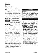
Introduction

Read this manual thoroughly before operating or servicing 
this unit.

Warnings, Cautions, and Notices

Safety advisories appear throughout this manual as 
required. Your personal safety and the proper operation of 
this machine depend upon the strict observance of these 
precautions.

Important Environmental Concerns

Scientific research has shown that certain man-made 
chemicals can affect the earth’s naturally occurring 
stratospheric ozone layer when released to the 
atmosphere. In particular, several of the identified 
chemicals that may affect the ozone layer are refrigerants 
that contain Chlorine, Fluorine and Carbon (CFCs) and 
those containing Hydrogen, Chlorine, Fluorine and 
Carbon (HCFCs). Not all refrigerants containing these 
compounds have the same potential impact to the 
environment. Trane advocates the responsible handling of 
all refrigerants-including industry replacements for CFCs 
and HCFCs such as saturated or unsaturated HFCs and 
HCFCs.

Important Responsible Refrigerant 
Practices

Trane believes that responsible refrigerant practices are 
important to the environment, our customers, and the air 
conditioning industry. All technicians who handle 
refrigerants must be certified according to local rules. For 
the USA, the Federal Clean Air Act (Section 608) sets forth 
the requirements for handling, reclaiming, recovering and 
recycling of certain refrigerants and the equipment that is 
used in these service procedures. In addition, some states 
or municipalities may have additional requirements that 
must also be adhered to for responsible management of 
refrigerants. Know the applicable laws and follow them.


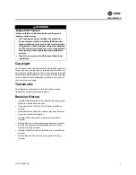
The three types of advisories are defined as follows:

WARNING

Indicates a potentially hazardous 
situation which, if not avoided, could 
result in death or serious injury.

CAUTION

s

Indicates a potentially hazardous 
situation which, if not avoided, could 
result in minor or moderate injury. It 
could also be used to alert against 
unsafe practices.

NOTICE

Indicates a situation that could result in 
equipment or property-damage only 
accidents.

WARNING

Proper Field Wiring and Grounding 
Required!

Failure to follow code could result in death or serious 
injury. All field wiring MUST be performed by qualified 
personnel. Improperly installed and grounded field 
wiring poses FIRE and ELECTROCUTION hazards. To 
avoid these hazards, you MUST follow requirements for 
field wiring installation and grounding as described in 
NEC and your local/state electrical codes. 

WARNING

Personal Protective Equipment (PPE) 
Required!

Failure to wear proper PPE for the job being undertaken 
could result in death or serious injury. Technicians, in 
order to protect themselves from potential electrical, 
mechanical, and chemical hazards, MUST follow 
precautions in this manual and on the tags, stickers, 
and labels, as well as the instructions below:

Before installing/servicing this unit, technicians 
MUST put on all PPE required for the work being 
undertaken (Examples; cut resistant gloves/sleeves, 
butyl gloves, safety glasses, hard hat/bump cap, fall 
protection, electrical PPE and arc flash clothing). 
ALWAYS refer to appropriate Material Safety Data 
Sheets (MSDS)/Safety Data Sheets (SDS) and OSHA 
guidelines for proper PPE.

When working with or around hazardous chemicals, 
ALWAYS refer to the appropriate MSDS/SDS and 
OSHA/GHS (Global Harmonized System of 
Classification and Labelling of Chemicals) guidelines 
for information on allowable personal exposure 
levels, proper respiratory protection and handling 
instructions.

If there is a risk of energized electrical contact, arc, or 
flash, technicians MUST put on all PPE in accordance 
with OSHA, NFPA 70E, or other country-specific 
requirements for arc flash protection, PRIOR to 
servicing the unit. NEVER PERFORM ANY 
SWITCHING, DISCONNECTING, OR VOLTAGE 
TESTING WITHOUT PROPER ELECTRICAL PPE AND 
ARC FLASH CLOTHING. ENSURE ELECTRICAL 
METERS AND EQUIPMENT ARE PROPERLY RATED 
FOR INTENDED VOLTAGE.

Summary of Contents for K01K12345

Page 1: ...training Improperly installed adjusted or altered equipment by an unqualified person could result in death or serious injury When working on the equipment observe all precautions in the literature and...

Page 2: ...n which if not avoided could result in minor or moderate injury It could also be used to alert against unsafe practices NOTICE Indicates a situation that could result in equipment or property damage o...

Page 3: ...ion sizes for gas heat sections figure in Installation chapter Updated Duct Connection section in Installation chapter Added Gas heat internal piping penetration location and Gas heat external piping...

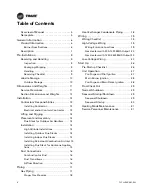
Page 4: ...stalling Outdoor Flue Stacks 14 Installing Indoor Flue Stacks 15 Installing Rain Hood Combustion Air Inlet 15 Installing Flue Stack for Hurricane Applica tions 15 Duct Connections 16 Combustion Air Du...

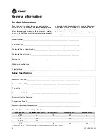
Page 5: ...handler section includes a nameplate label see Figure 1 which identifies the type of section customer tagging information the unit serial number the unit order number the build section position for in...

Page 6: ..._________________________________________ Altitude Above Sea Level___________________________________________________________________ Calorific Value___________________________________________________...

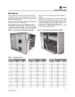
Page 7: ...gure 2 The external vestibule if required ships attached to the gas heat section Some heaters have gas train components in an internal vestibule see Figure 3 Refer to Table 2 for vestibule locations F...

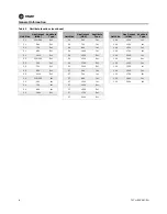
Page 8: ...25 560 Ext 50 1750 Ext 120 1000 Int 25 700 Ext 50 2000 Ext 120 1250 Int 25 860 Ext 57 560 Int 120 1500 Int 25 1000 Ext 57 700 Int 120 1750 Int 30 320 360 Int 57 860 Int 120 2000 Int 30 560 Int 57 100...

Page 9: ...removed before assembly to the air handler Instruction Manuals Individual instruction manuals for all of the gas train components such as flame control relay valves pressure switches and actuators sh...

Page 10: ...or units that will be installed indoors However when outdoor storage is necessary several things must be done to prevent damage Note Keep the equipment on the original wooden blocks skid for protectio...

Page 11: ...ltage panel 61 61 61 61 61 61 61 61 64 64 64 64 64 64 64 64 64 64 64 64 64 64 64 64 64 D internal starter or VFD 48 48 48 48 48 48 48 48 48 48 48 48 48 48 48 48 48 48 48 48 48 48 48 48 48 E fan 48 48...

Page 12: ...75 85 50 92 50 107 50 119 75 119 75 Width 93 50 100 00 112 50 125 50 125 50 140 50 140 50 154 50 182 00 Height for outdoor unit includes base drip lip b 69 25 75 00 75 00 84 38 94 13 97 63 112 63 124...

Page 13: ...o the gas heat system if thesupply fan isshut off The gas heat system must not operate without the supply fan providing airflow All wiring must comply with applicable local and National Electric Code...

Page 14: ...ove the flue from inside the unit once the unit is assembled Installation High Altitude Installations Adjustment of gas train linkages is not normally required However for high altitude installations...

Page 15: ...r the combustion air opening ship loose and must be installed at the job site The assembly consists of the hood butyl tape and number 10 screws Install butyl tape between the hood and the side panel o...

Page 16: ...additional static pressure of the inlet air duct may change the fuel air ratio slightly necessitating system adjustment Separated combustion can be a desirable option but will require more field insta...

Page 17: ...on and Deadly Gases Never solder braze or weld on refrigerant lines or any unit components that are above atmospheric pressure or where refrigerant may be present Always remove refrigerant by followin...

Page 18: ...he same side as the gas train located inside the piping vestibule Since the drain line is equipped with a shut off valve a condensate p trap is not required but may be installed for convenience to avo...

Page 19: ...ield wiring poses FIRE and ELECTROCUTION hazards To avoid these hazards you MUST follow requirements for field wiring installation and grounding as described in NEC and your local state electrical cod...

Page 20: ...power the transformer TRANS1 Low Voltage Wiring The gas heat control system requires a binary signal for on off control Provide an interlock in the start stop signal circuit with the air handler supp...

Page 21: ...Wiring CLCH SVX08C EN 21 Figure 16 Natural gas 200 320 MBh 10 1 turndown...

Page 22: ...Wiring 22 CLCH SVX08C EN Figure 17 Natural gas 360 1000 MBh 3 1 and 10 1 turndown and propane 200 1000 MBh...

Page 23: ...Wiring CLCH SVX08C EN 23 Figure 18 Single phase natural gas and propane 1250 2000 MBh 3 1 and 10 1 turndown...

Page 24: ...Wiring 24 CLCH SVX08C EN Figure 19 3 Phase propane and natural gas 1250 2000 MBh 3 1 and 10 1 turndown with power exhaust...

Page 25: ...Wiring CLCH SVX08C EN 25 Figure 20 Natural gas and propane1250 2400 MBh 20 1 turndown...

Page 26: ...w g Attach another manometer to the burner manifold if optional gauge or sensor is not selected to check the burner manifold pressure when the unit is operational Typical pressure should be between 2...

Page 27: ...er assembly The following safety limit contracts should be closed HLl1 high temperature limit Al1 airflow interlock air handling fan should either be running or started 60 seconds after call for heat...

Page 28: ...ignition transformer and automatic gas valves will energize With the manual gas cocks closed the burner should go into a safety lockout condition The flame safeguard will have to be reset manually Tur...

Page 29: ...luminate The modulating gas valve actuator starts to open and the main light on the flame relay module should illuminate Note that it could take as long as 30 seconds for the actuator to fully open 6...

Page 30: ...d drain any accumulated condensate 3 Check all electrical terminals for tight connections 4 Open all manual gas valves and ensure that these valves operate freely 5 Check the air shutter and modulatin...

Page 31: ...densate from heat exchanger Weekly This task only needs to be done if the unit runs for extended hours at low fire Clean air inlet louver Monthly Use brush and vacuum cleaner Clean combustion air blow...

Page 32: ...gh Limit This switch trips due to a high temperature condition in the gas heat section Allow the air handler fan to run and cool heat exchanger The switch must be manually reset when the heat exchange...

Page 33: ...quate grounding and that it is properly located in the flame Also ensure that temperature at flame rod insulator is no greater than 500 F 260 C Perform Ignition Interference Test per component manufac...

Page 34: ......

Page 35: ......

Page 36: ...and protect food and perishables and increase industrial productivity and efficiency We are a global business committed to a world of sustainable progress and enduring results ingersollrand com Ingers...

Reviews: