Piping
18
CLCH-SVX08C-EN
Proper Gas Pressure
•
To assure sufficient gas pressure at the unit, use
appropriately sized gas pipe for unit capacity. Refer to
the National Fuel Gas Code for pipe sizing information.
•
Select an appropriately sized gas pressure regulator to
assure the required gas supply pressure is maintained
at the unit.
•
Required gas pressure to the gas train is 7 to 14 inches
wc (0.25 to 0.5 psig) for units through 2400 MBh. Note
that a minimum of 9 inches wc (0.32 psig) is required
for 1250-2000 MBh heaters with 10:1 turndown
capability. For all size units, do not exceed 14 inches wc
(0.5 psig) inlet gas pressure.
•
Gas pressure and volume must be maintained and
stable at high fire.
•
If the gas pressure regulator serves more than one
heating unit, it must be sized appropriately to ensure
that the inlet gas pressure at each unit is 7 to 14 inches
wc while all burners are firing. Nine inches wc is
required for 1250 to 2000 10:1 turndown heaters. Gas
pressure must not exceed 14 inches wc when all units
are off.
•
Check the gas supply pressure before making the final
connection to the unit. If the gas pressure is too high,
damage to the gas valve could occur.
Heat Exchanger Condensate
Piping
Condensate usually does not form in the heat exchanger
during normal heating operation. However, if the unit
operates for extended periods of time at very low fire, or
if the air handler serves as a cooling unit also, condensate
can form in the heat exchanger and should be removed.
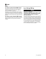
All units are equipped with a condensate drain and drain
valve. The condensate drain is on the same side as the gas
train located inside the piping vestibule.
Since the drain line is equipped with a shut-off valve, a
condensate p-trap is not required, but may be installed for
convenience to avoid periodic manual draining. If a p-trap
and drain is to be connected to the condensate drain line,
consult local plumbing codes for disposal of the
condensate may be a slightly acidic solution.
as a guideline for p-trap construction.
The use of a tee-fitting at the connection to the condensate
outlet is recommended. This allows for priming and
cleaning the trap. If a tee-fitting is used, be sure to furnish
a plug or cap for the clean out opening. Be sure to replace
the plug after priming or cleaning the trap.
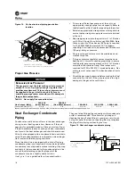
Figure 14.
Gas heat external piping penetration
location
NOTICE
Excessive Gas Pressure!
The gas pressure at the inlet to the gas train must not
exceed 14 in. wc. A properly sized gas regulator that
provides a maximum of 14 in wc. of gas pressure, must
be supplied in the gas inlet line to unit. Failure to
maintain proper gas pressure could result in damage to
the gas train components.
Combustion Air Inlet
Shaded area is "OK" for gas inlet pipe
Do not install gas pipe in access door or combustion air inlet
Access
Door
Access
Door
Flue
External Vestibule
Combustion Air Inlet
Combustion Air
Vented Floor Inlet
Table 6.
Gas supply line connection sizes
Gas Output (MBh)
200-320
(Midco Burner)
200-560
(Non-Midco Burner)
700-1000
1250-1750
2000-2400
Connection Size (NPT)
3/4 in.
1 in.
1 1/4 in.
1 1/2 in.
2 in.
Note:
If gas output is between 200 and 320 MBh, confirm burner manufacturer before sizing gas supply line.
Figure 15. Heat exchanger condensate piping
L = H + J + diameter where:
H = 5 inches
J = 2.5 inches
L
H
J
Tee with cap
Normal operation
Shut-off Valve
1/2” NPT

