background image

12

WSHP-SVX02A-EN

Cleaning and Flushing 

the Water Loop

After the piping system is complete, 
the flexible hose connectors should be 
doubled back to complete the water 
circuit external to the unit (avoiding 
trash settle-out in the condenser). Fig-
ure 4
. An extra pipe may be necessary 
to connect the hose kits. See Page 14 
for antifreeze/water mixture by vol-
ume.

(1)

 Water circulation system should be 

filled with clean water using the water 
make up connections. Note: Air vents 
should be opened during filling.

(2)

 With the air vents closed, start the 

circulating pump and then crack the air 
vents to bleed off the trapped air, as-
suring circulation through all compo-
nents of the system.
Note: Make up water must be available 
to the system to replace the volume 
formerly occupied by the air that is 

bled off.

(3)

 With the air vented and the water 

circulating, the entire system 
should be checked for leaks with re-
pairs made as required.

(4)

 Operate the supplementary 

heat system making checks per 
manufacturer’s instructions. Dur-
ing this operation, visual checks 
should be made for leaks that may 
have occurred due to increased 
heat. Repair as required.

(5)

 Open the system at the lowest 

point for the initial blow down 
(making sure the make up water is 
equal to the water being dumped). 
Continue blow down until the water 
leaving the drain runs clear, but not 
less than 2 hours.

(6)

 Shut down pumps and supplemen-

tary heat system. Reconnect the hoses 
placing the water-to-refrigerant heat 
exchanger in the water circulating sys-
tem.

Note: Vents should be open when the 
pumps and supplementary heat sys-

tem are shut down.

Installation

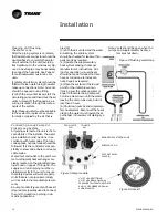
SHUT-OFF 3-WAY

PURGING CAP (2)

BRONZE OR CAST IRON PUMP

FROM UNIT’S 

W.O.

TO UNIT’S 

W.I.

Figure 5 Pump module

Figure 6: Hose kit

1" MPT x BARB FITTINGS,
1" MPT x BARB ELBOWS with
PRESSURE TEMPERATURE PORTS,
AND 10’ OF RUBBER HOSE with

4 HOSE CLAMPS.

VALVE (2)

Connecting a 

Loop Pump Kit 

Closed Loop System

All piping external to the unit is the re-
sponsibility of the installer. The water 
pipe installation must be done in ac-
cordance with local codes. If no local 
code applies, national codes should be 
followed. It is the contractor’s respon-
sibility to know and adhere to all appli-
cable codes.
Water inlet and outlet to the unit’s wa-
ter-to-refrigerant heat exchanger are 
clearly marked on the submittal draw-
ings found on pages 7 through 9. The 
supply and return piping must be in-
stalled correctly to the unit to ensure 
the safety devices will work properly. 
Units that are not piped accordingly 
will not obtain the manufacturers war-
ranty.
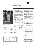
A pump module (Figure 5) and hose kit 
(Figure 6) are typically used to connect 
the unit to closed loop piping in do-
mestic applications.

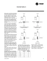
Figure 4: Flushing water loop

Summary of Contents for EXWA

Page 1: ...WSHP SVX02A EN Models A and later Design Sequence Installation Owner Diagnostics Water to Water Water Source Heat Pump Models WPWD GSWD and EXWA WPWD 024 072 60 HZ GSWD 024 072 60 HZ EXWA 240 60 HZ ...

Page 2: ...system to knowingly vent or release any CFC or HCFC refrigerant Minimal releases air purges or refrigerant hoses associated with good faith attempts to recapture or recycle are exempt from the ban on venting Responsible Refrigerant Practices Trane believes that responsible refrigerant practices are important to the environment our customers and the air conditioning industry All technicians who han...

Page 3: ... Information 5 Dimensions Weights 6 Installation Instructions 10 Electrical Requirements 19 Pre Startup Checklist 20 Startup Commissioning 21 Sequence of Operation 21 Operating Pressures 22 30 Startup Checklist Log 24 Maintenance 25 Warranty Information 26 Troubleshooting Checklist 28 Unit Wiring 29 ...

Page 4: ...chrader caps to assure that refrigerant leakage does not occur WARNING Microbial Growth Wet interior unit insulation can become an amplification site for microbial growth mold which may cause odors and damage to the equipment and building materials If there is evidence of microbial growth mold on the interior insulation the insulation should be removed and replaced prior to operating the system Jo...

Page 5: ...ption in clude a low pressure switch and a freezestat to prevent compressor op eration during low temperature activi ty The switch is set to activate at refrigerant pressures of 35 psig or 7 psig to fit most applications A high pressure switch prevents com pressor operation during high or ex cessive discharge pressures exceeding 395 psig The lockout relay communicates the low or high pressure situ...

Page 6: ...ent or property only damage Dimensions Weights Clearance Figure 1 Mechanical clearances Unit Location and Clearances Locate the unit in an indoor area The ambient temperature surrounding the unit must not be less than 45 F Do not locate the unit in areas subject to freezing Attention should be given to service clearance and technician safety The unit access panels may be easily re moved There must...

Page 7: ...WSHP SVX02A EN 7 Dimensions WPWD GSWD 024 036 ...

Page 8: ...8 WSHP SVX02A EN Dimensions WPWD GSWD 042 072 ...

Page 9: ...WSHP SVX02A EN 9 Dimensions EXWA 240 ...

Page 10: ...gerant tubing has clearance from adjacent parts WARNING Hazardous Voltage Disconnect all electric power including remote disconnects before servicing Follow proper lockout tagout procedures to ensure the power can not be inadvertently energized Failure to disconnect power before servicing could result in death or serious injury Main Electrical 5 Verify the power supply complies with the unit namep...

Page 11: ...stem Note The source for a water to water heat pump is typically a boiler cooling tower or geothermal loop The load for a water to water heat pump is typically fresh air unit s fan coil s hydronic coil s radiant heat wall fin or potable water The source and load connections for the 2 ton through 6 ton equipment is on the right hand side of the unit The 20 ton equipment incorporates the source side...

Page 12: ...ter being dumped Continue blow down until the water leaving the drain runs clear but not less than 2 hours 6 Shut down pumps and supplemen tary heat system Reconnect the hoses placing the water to refrigerant heat exchanger in the water circulating sys tem Note Vents should be open when the pumps and supplementary heat sys tem are shut down Installation SHUT OFF 3 WAY PURGING CAP 2 BRONZE OR CAST ...

Page 13: ...f the unit Extreme care should be taken by the installing contractor to prevent dirt or other for eign matter from entering the pipes or piping components during construc tion Pipes should be capped until they are in place and ready to be connected to the system 4 Install the Trane loop pump mod ule See installation manual WSHPC IN 5 or 72 9006 03 for instructions If the unit does not contain a Tr...

Page 14: ...d antifreeze solution to pre vent the earth loop water from freez ing inside the heat exchanger Methanol and glycols are the most commonly used antifreeze solutions Consult your geothermal unit supplier for locally approved solutions in your area Propylene glycol is not recommended in installations where the water tem perature are expected to fall below 30 F At extreme temperatures the viscosity i...

Page 15: ...rge hose System Pressurization 1 Rotate both valves 1 and 2 to the Position D to pressurize the system 2 Examine all internal unit fittings or connections for leaks 3 After check ing for leaks the system is ready to be flushed Note There may be a certain amount of entrained air left in the loop system Cleaning and Flushing the Water Loop All installations must be thoroughly flushed to remove air a...

Page 16: ...nal Electric Code NEC latest edition Location of the applicable electric ser vice entrance for HIGH line voltage may be found on the unit submittal at the front of this manual pages 7 through 9 The high voltage connection is made at the 1TB1 terminal block for the 20 ton equipment and at 1K1 for the 2 ton through 6 ton equipment The ter minal block or contactor is located in side the unit control ...

Page 17: ... voltage connection diagrams are shown in Figure 9 Optional desuper heater fuse installation shown in Fig ure 10 Table 4 24V AC conductors Distance from unit to Control Recommended Wire Size 000 460 feet 18 gauge 461 732 feet 16 gauge 733 1000 feet 14 gauge Table 5 Deluxe controller diagnostic LEDs Color Green Color Red Controller Mode LED1 LED2 LED3 OFF OFF OFF Control OFF ON OFF OFF Normal Compr...

Page 18: ...r to install ing the unit The freezestat is easily ac cessible from the top service door WARNING Hazardous Voltage Disconnect all electric power in cluding remote disconnects be fore servicing Follow proper lockout tagout procedures to en sure the power can not be inad vertently energized Failure to disconnect power before servic ing could result in death or seri ous injury Changing a Freezestat a...

Page 19: ... 8 30 380 415 50 3 342 456 7 1 44 0 1 8 9 15 0 0 4 9 3 15 0 460 60 3 414 506 7 1 44 0 1 8 9 15 0 4 9 3 15 WPWD060 208 230 60 1 197 253 28 0 169 0 1 35 0 60 0 4 35 4 60 208 230 60 3 197 253 20 0 123 0 1 25 0 45 0 4 25 4 45 380 415 50 3 342 456 7 5 49 5 1 9 4 15 0 0 4 9 8 15 0 460 60 3 414 506 7 5 49 5 1 9 4 15 0 4 9 8 15 575 60 3 517 633 6 4 40 0 1 8 0 15 0 4 8 4 15 WPWD072 208 230 60 1 197 253 32 ...

Page 20: ...r to refrigerant heat exchanger be done in accor dance with the Closed Loop Ground Source Heat Pump Systems Installation Guide ____ Is vibration isolation provided i e unit isolation pad hosekits ____ Is unit serviceable See clearance specifications on page 6 ____ Are the low high side pressure temperature caps secure and in place ____ Are all the unit access panels secure and in place ____ Is the...

Page 21: ...data plate ratings the suction line should be cool with no frost observed in the refrigerant circuit 4 Check the cooling refrigerant pressures against values in Table OP1 Page 22 5 Turn the system control switch to the OFF position Unit should stop running and the reversing valve should de ener gize 6 Leave unit off for approximately FIVE minutes to allow for pressure equalization 7 Turn the therm...

Page 22: ...49 59 188 228 49 59 238 278 EXWA 240 86 61 71 111 151 84 94 205 245 87 97 259 299 Table OP 2 Heating mode operating pressures Unit Size Entering Load Degree F Entering Source Temperature Degree F 50 68 104 Suction Pressure Discharge Pressure Suction Pressure Discharge Pressure Suction Pressure Discharge Pressure EXWA 240 75 46 56 160 200 65 75 170 210 86 96 183 223 EXWA 240 104 49 59 245 285 68 78...

Page 23: ...for heating the temperature drop is from 2 F 13 F Pressure Using the P T ports and one 0 60 psi pressure gauge with the P T port adapter measure the pressure difference between the water in and water out connections Compare the pressure differential to Table 6 to determine flow Start up Checklist and Log Use the form on page 24 to log system and unit temperatures during start up Table 6 Cooling wa...

Page 24: ...bleshooting and costly system failures complete the following checks and data entries before the system is put into full operation MODE Entering fluid temperature Leaving fluid temperature Temperature differential Water coil heat exchanger Water Pressure IN Water coil heat exchanger Water Pressure OUT Pressure Differential HEAT F COOL F F F F F PSIG PSIG PSIG PSIG PSIG PSIG COMPRESSOR Amps Volts D...

Page 25: ...scaling as a result of bad water the heat exchanger will have to be back flushed and cleaned with a chemical that will remove the scale This service should be performed by an experi enced service person Maintenance WARNING Hazardous Chemicals Coil cleaning agents can be either acidic or highly alkaline Handle chemical carefully Proper han dling should include goggles or face shield chemical resist...

Page 26: ...ed 18 months from shipment Extended Warranty The optional extended warranty is a second through fifth year warranty The time starts at the end of standard 1 year coverage through the fifth year These extended warranties apply only to new equipment installed in domestic Trane Commercial Systems Group sales territories and must be ordered prior to start up Warranty Information ...

Page 27: ...ion broken or disconnected wires etc If everything appears to be in or der but the unit still fails to operate properly refer to the troubleshooting chart on page 28 General Operation The standard model is designed for in door installation When the unit is in stalled in an unconditioned space the unit may not start in cool weather ap proximately 45 F It may then be nec essary to start the unit in ...

Page 28: ...ase water flow to unit X Water too hot Decrease temperature X X Overcharged with refrigerant Decrease charge X X Defective pressure switch Check or replace High head pressure X Trash in heat exchanger Backflush X Low water flow Increase GPM X X Overcharge of refrigerant Decrease charge X X Non condensable in system Evacuate and recharge by weight X X Water too hot Decrease temperature Low suction ...

Page 29: ...WSHP SVX02A EN 29 Unit Wiring 2 ton through 6 Ton Equipment ...

Page 30: ...30 WSHP SVX02A EN Unit Wiring 20 Ton Equipment ...

Page 31: ...and specifications without notice Literature Order Number WSHP SVX02A EN File Number SV UN WSHP SVX02A 8 02 Supersedes WSHPC IOM 4 and 72 9036 02 Stocking Location Inland Trane An American Standard Company www trane com For more information contact your local district office or e mail us at comfort trane com ...

Reviews: