


CG-SVX17D-EN
77
Installation - Electrical
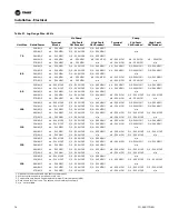
Table 32. Electrical Data - 50Hz
Unit
Size
Rated
Power
Number
Circuits
Qty
Comp
Qty
Fans
Fan Motor
Power (kW)
Cond Fan
FLA
Compressor
RLA¹ ²
Compressor
LRA¹ ³
MCA
MOPD
20
400/50/3
1
2
2
1
2.4
17-17
142-142
46
60
26
400/50/3
1
2
2
1
2.4
21-21
158-158
55
70
30
400/50/3
1
2
3
1
2.4
27-27
160-160
71
90
35
400/50/3
1
2
3
1
2.4
27-33
160-215
79
110
40
400/50/3
2
4
4
1
2.4
17-17/17-17
142-142/142-142
85
100
52
400/50/3
2
4
4
1
2.4
21-21/21-21
158-158/158-158
102
110
60
400/50/3
2
4
6
1
2.4
27-27/27-27
160-160/160-160
133
150
70
400/50/3
2
4
6
1
2.4
27-33/33-27
160-215/215-160
147
175
80
400/50/3
2
4
6
1
2.4
33-33/33-33
215-215/215-215
160
175
90
400/50/3
2
4
6
1
2.4
33-43/43-33
215-260/260-215
181
200
100
400/50/3
2
4
8
1
2.4
43-43/43-43
260-260/260-260
204
225
110
400/50/3
2
4
8
1
2.4
43-47/47-43
260-320/260-320
214
250
120
400/50/3
2
4
8
1
2.4
47-47/47-47
320-320/320-320
223
250
1. RLA - Rated Load Amps - Rated in accordance with UL Standard 1995.
2. LRA - Locked Rotor Amps - Based on full winding starts.
3. MCA - Minimum Circuit Ampacity - 125 percent of largest compressor RLA plus 100 percent of all other loads.
4. MOPD or Max fuse size - 225 percent of the largest compressor RLA plus all other loads.
5. Local codes may take precedence.
6. Voltage Utilization Range: +/- 10% of rated voltage
Rated voltage (use range):
400/50/3 (360-440)
7. One separate 120/50/1, 15 amp customer provided power connection is required to power the heaters.
8. n/a - not available
9. Pump package not available with 50 Hz units.
Table 33. Lug Size Range - 50 Hz
Unit
Size
Rated Power
Terminal Blocks
Std Fault
Ckt Breaker¹
High Fault
Ckt Breaker¹
20
400/50/3
#6 - 350 MCM
#14 - 1/0
#14 - 1/0
26
400/50/3
#6 - 350 MCM
#14 - 1/0
#14 - 1/0
30
400/50/3
#6 - 350 MCM
#14 - 1/0
#14 - 1/0
35
400/50/3
#6 - 350 MCM
#14 - 1/0
#14 - 1/0
40
400/50/3
#4 - 500 MCM
#6 - 350 MCM
#6 - 350 MCM
52
400/50/3
#4 - 500 MCM
#6 - 350 MCM
#6 - 350 MCM
60
400/50/3
#4 - 500 MCM
#6 - 350 MCM
#6 - 350 MCM
70
400/50/3
#4 - 500 MCM
#6 - 350 MCM
#6 - 350 MCM
80
400/50/3
#4 - 500 MCM
#6 - 350 MCM
#6 - 350 MCM
90
400/50/3
#4 - 500 MCM
#6 - 350 MCM
#6 - 350 MCM
100
400/50/3
#4 - 500 MCM
3/0 - 500 MCM²
3/0 - 500 MCM²
110
400/50/3
#4 - 500 MCM
3/0 - 500 MCM²
3/0 - 500 MCM²
120
400/50/3
#4 - 500 MCM
3/0 - 500 MCM²
3/0 - 500 MCM²
1. Optional circuit breaker and high fault circuit breaker.
2. Will accept two conduits per phase in this size.
3. Copper wire only, based on nameplate Minimum Circuit Ampacity (MCA).
4. Data shown for circuit one. The second circuit is always the same.
5. n/a - not available
Summary of Contents for CGAM
Page 44: ...44 CG SVX17D EN Installation Mechanical Figure 39 CGAM W 80 120 Ton Rigging X Z Y ...
Page 104: ...104 CG SVX17D EN CGAM Operating Principles Figure 79 10 15 Ton Compressor Internal Components ...
Page 105: ...CG SVX17D EN 105 CGAM Operating Principles Figure 80 15 30 Ton Compressor Internal Components ...
Page 135: ...CG SVX17D EN 135 Controls Interface Figure 87 Diagnostic View ...
Page 149: ...CG SVX17D EN 149 Unit Start Up Procedures Figure 95 Power Up to Starting ...
Page 185: ...CG SVX17D EN 185 Unit Wiring S2075 1 20 35 Ton Slant Frame Table of Contents ...
Page 186: ...186 CG SVX17D EN Unit Wiring S2075 2 20 35 Ton Slant Frame Legend ...
Page 187: ...CG SVX17D EN 187 Unit Wiring 20 35 Ton Slant Frame Legend ...
Page 188: ...188 CG SVX17D EN Unit Wiring S2075 3 20 35 Ton Slant Frame Notes ...
Page 189: ...CG SVX17D EN 189 Unit Wiring 20 35 Ton Slant Frame Notes ...
Page 190: ...190 CG SVX17D EN Unit Wiring S2075 4 20 35 Ton Slant Frame Compressor Power Circuit 1 ...
Page 191: ...CG SVX17D EN 191 Unit Wiring 20 35 Ton Slant Frame Compressor Power Circuit 1 ...
Page 192: ...192 CG SVX17D EN Unit Wiring S2075 6 20 35 Ton Slant Frame Fan Power Circuit 1 ...
Page 193: ...CG SVX17D EN 193 Unit Wiring 20 35 Ton Slant Frame Fan Power Circuit 1 ...
Page 194: ...194 CG SVX17D EN Unit Wiring S2075 8 20 35 Ton Slant Frame Pump Power Control ...
Page 195: ...CG SVX17D EN 195 Unit Wiring 20 35 Ton Slant Frame Pump Power Control ...
Page 196: ...196 CG SVX17D EN Unit Wiring S2075 9 20 35 Ton Slant Frame Compressor Control ...
Page 197: ...CG SVX17D EN 197 Unit Wiring 20 35 Ton Slant Frame Compressor Control ...
Page 198: ...198 CG SVX17D EN Unit Wiring S2075 10 20 35 Ton Slant Frame Fan Control 2 3 Fan Units ...
Page 199: ...CG SVX17D EN 199 Unit Wiring 20 35 Ton Slant Frame Fan Control 2 3 Fan Units ...
Page 200: ...200 CG SVX17D EN Unit Wiring S2075 12 20 35 Ton Slant Frame Common Control ...
Page 201: ...CG SVX17D EN 201 Unit Wiring 20 35 Ton Slant Frame Common Control ...
Page 202: ...202 CG SVX17D EN Unit Wiring S2075 13 20 35 Ton Slant Frame Common Control ...
Page 203: ...CG SVX17D EN 203 Unit Wiring 20 35 Ton Slant Frame Common Control ...
Page 204: ...204 CG SVX17D EN Unit Wiring S2075 14 20 35 Ton Slant Frame Freeze Protection ...
Page 205: ...CG SVX17D EN 205 Unit Wiring 20 35 Ton Slant Frame Freeze Protection ...
Page 206: ...206 CG SVX17D EN Unit Wiring V2075 1 40 70 Ton V Frame Table of Contents ...
Page 207: ...CG SVX17D EN 207 Unit Wiring 40 70 Ton V Frame Table of Contents ...
Page 208: ...208 CG SVX17D EN Unit Wiring V2075 2 40 70 Ton V Frame Legend ...
Page 209: ...CG SVX17D EN 209 Unit Wiring 40 70 Ton V Frame Legend ...
Page 210: ...210 CG SVX17D EN Unit Wiring V2075 3 40 70 Ton V Frame Notes ...
Page 211: ...CG SVX17D EN 211 Unit Wiring 40 70 Ton V Frame Notes ...
Page 212: ...212 CG SVX17D EN Unit Wiring V2075 4 40 70 Ton V Frame Compressor Power Circuit 1 ...
Page 213: ...CG SVX17D EN 213 Unit Wiring 40 70 Ton V Frame Compressor Power Circuit 1 ...
Page 214: ...214 CG SVX17D EN Unit Wiring V2075 5 40 70 Ton V Frame Compressor Power Circuit 2 ...
Page 215: ...CG SVX17D EN 215 Unit Wiring 40 70 Ton V Frame Compressor Power Circuit 2 ...
Page 216: ...216 CG SVX17D EN Unit Wiring V2075 6 40 70 Ton V Frame Fan Power Circuit 1 ...
Page 217: ...CG SVX17D EN 217 Unit Wiring 40 70 Ton V Frame Fan Power Circuit 1 ...
Page 218: ...218 CG SVX17D EN Unit Wiring V2075 7 40 70 Ton V Frame Fan Power Circuit 2 ...
Page 219: ...CG SVX17D EN 219 Unit Wiring 40 70 Ton V Frame Fan Power Circuit 2 ...
Page 220: ...220 CG SVX17D EN Unit Wiring V2075 8 40 70 Ton V Frame Pump Power Control ...
Page 221: ...CG SVX17D EN 221 Unit Wiring 40 70 Ton V Frame Pump Power Control ...
Page 222: ...222 CG SVX17D EN Unit Wiring V2075 9 40 70 Ton V Frame Compressor Control ...
Page 223: ...CG SVX17D EN 223 Unit Wiring 40 70 Ton V Frame Compressor Control ...
Page 224: ...224 CG SVX17D EN Unit Wiring V2075 10 40 70 Ton V Frame Fan Control 2 3 Fan Units ...
Page 225: ...CG SVX17D EN 225 Unit Wiring 40 70 Ton V Frame Fan Control 2 3 Fan Units ...
Page 226: ...226 CG SVX17D EN Unit Wiring V2075 12 40 70 Ton V Frame Common Control ...
Page 227: ...CG SVX17D EN 227 Unit Wiring 40 70 Ton V Frame Common Control ...
Page 228: ...228 CG SVX17D EN Unit Wiring V2075 13 40 70 Ton V Frame Common Control ...
Page 229: ...CG SVX17D EN 229 Unit Wiring 40 70 Ton V Frame Common Control ...
Page 230: ...230 CG SVX17D EN Unit Wiring V2075 14 40 70 Ton V Frame Freeze Protection ...
Page 231: ...CG SVX17D EN 231 Unit Wiring 40 70 Ton V Frame Freeze Protection ...
Page 232: ...232 CG SVX17D EN Unit Wiring W2075 1 80 130 Ton W Frame Table of Contents ...
Page 233: ...CG SVX17D EN 233 Unit Wiring 80 130 Ton W Frame Table of Contents ...
Page 234: ...234 CG SVX17D EN Unit Wiring W2075 2 80 130 Ton W Frame Legend ...
Page 235: ...CG SVX17D EN 235 Unit Wiring 80 130 Ton W Frame Legend ...
Page 236: ...236 CG SVX17D EN Unit Wiring W2075 3 80 130 Ton W Frame Notes ...
Page 237: ...CG SVX17D EN 237 Unit Wiring 80 130 Ton W Frame Notes ...
Page 238: ...238 CG SVX17D EN Unit Wiring W2075 4 80 130 Ton W Frame Compressor Power Circuit 1 ...
Page 239: ...CG SVX17D EN 239 Unit Wiring 80 130 Ton W Frame Compressor Power Circuit 1 ...
Page 240: ...240 CG SVX17D EN Unit Wiring W2075 5 80 130 Ton W Frame Compressor Power Circuit 2 ...
Page 241: ...CG SVX17D EN 241 Unit Wiring 80 130 Ton W Frame Compressor Power Circuit 2 ...
Page 242: ...242 CG SVX17D EN Unit Wiring W2075 6 80 130 Ton W Frame Fan Power Circuit 1 ...
Page 243: ...CG SVX17D EN 243 Unit Wiring 80 130 Ton W Frame Fan Power Circuit 1 ...
Page 244: ...244 CG SVX17D EN Unit Wiring W2075 7 80 130 Ton W Frame Fan Power Circuit 2 ...
Page 245: ...CG SVX17D EN 245 Unit Wiring 80 130 Ton W Frame Fan Power Circuit 2 ...
Page 246: ...246 CG SVX17D EN Unit Wiring W2075 8 80 130 Ton W Frame Pump Power Control ...
Page 247: ...CG SVX17D EN 247 Unit Wiring 80 130 Ton W Frame Pump Power Control ...
Page 248: ...248 CG SVX17D EN Unit Wiring W2075 9 80 130 Ton W Frame Compressor Control ...
Page 249: ...CG SVX17D EN 249 Unit Wiring 80 130 Ton W Frame Compressor Control ...
Page 250: ...250 CG SVX17D EN Unit Wiring W2075 10 80 130 Ton W Frame Fan Control 2 3 Fan Units ...
Page 251: ...CG SVX17D EN 251 Unit Wiring 80 130 Ton W Frame Fan Control 2 3 Fan Units ...
Page 252: ...252 CG SVX17D EN Unit Wiring W2075 11 80 130 Ton W Frame Fan Control 4 5 Fan Units ...
Page 253: ...CG SVX17D EN 253 Unit Wiring 80 130 Ton W Frame Fan Control 4 5 Fan Units ...
Page 254: ...254 CG SVX17D EN Unit Wiring W2075 12 80 130 Ton W Frame Common Control ...
Page 255: ...CG SVX17D EN 255 Unit Wiring 80 130 Ton W Frame Common Control ...
Page 256: ...256 CG SVX17D EN Unit Wiring W2075 13 80 130 Ton W Frame Common Control ...
Page 257: ...CG SVX17D EN 257 Unit Wiring 80 130 Ton W Frame Freeze Protection ...
Page 258: ...258 CG SVX17D EN Unit Wiring W2075 14 80 130 Ton W Frame Freeze Protection ...
Page 259: ...CG SVX17D EN 259 Unit Wiring 80 130 Ton W Frame Common Control ...
Page 260: ...260 CG SVX17D EN Unit Wiring 2076 1 Field Wiring Diagram ...
Page 261: ...CG SVX17D EN 261 Unit Wiring C TRANE Field Wiring Diagram ...
Page 262: ...262 CG SVX17D EN Unit Wiring 2076 2 FUSE Field Wiring Diagram Notes ...


