


10
UHM-DHM-SF-1H
Service Facts
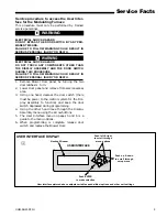
9. “IGNITION” will now be displayed in the “STA-
TUS” section of the User Interface menu.
10. After 45 seconds, the IFC signals the indoor
blower motor to run at the programmed ignition
sequence speed.
11. The IFC then signals the variable speed inducer
motor drive board to ramp down to the corre-
sponding speed to keep PS1 closed. The reduction
of the vent motor speed in steps allows the gas
flow through the gas valve to also be reduced in
steps, decreasing the chance of burner flame out.
The W1 heating capacity is 40%. The IFC will
also decrease the indoor blower motor speed.
Thermostat call for W2 after W1
12. R and W2 thermostat contacts close signaling a
call for W2 heat. The IFC then signals the vari-
able speed inducer drive to ramp up the vent
motor allowing flow through the gas valve to also
be increased in 3% steps.
13. If the call for W2 remains, this 3% increase will
be repeated every 1 minute until the capacity
requested is 100%. The IFC will also increase the
indoor blower motor speed in appropriate steps.
W2 satisfied, W1 still called for
14. R and W2 thermostat contacts open signaling
that W2 heating requirements have been satis-
fied. The IFC will signal the variable speed vent
motor to slow down to its learned W1 speed. The
gas valve will reduce the gas flow to 40% capacity
and the indoor blower motor speed will be re-
duced.
W1 satisfied
15. R and W1 thermostat contacts open signaling
that W1 heating requirements have been satis-
fied. The gas valve will be de-energized and gas
flow will cease. The variable speed vent motor
will de-energize approximately after a 5 second
post purge.
The indoor blower motor will be de-energized
after the fan off delay period has ended. (The
indoor blower heat fan off delay is field selectable
and can be adjusted using the User Interface
menu. It is factory set at 100 seconds but can be
set to 60, 140, or 180 seconds)
Thermostat call for heat (1 stage heating ther-
mostat)
16. W1 and W2 must be jumpered at the IFC. R and
W1 contacts close signaling the control board
(IFC) to run its self- check routine. After the
control has verified that all safeties are closed
and PS1, PS2, and PS3 pressure switch contacts
are open, the IFC signals the variable speed
inducer drive to start the vent motor at the speed
needed to close pressure switches PS1 and PS2.
Note:
The furnace lights at approximately 65% of capacity
.
17. PS1 and PS2 close.
18. The IFC receives a 24 VAC signal from PS1 and
PS2 when they close. This verifies the vent
motor is moving the correct amount of combus-
tion air through the furnace and the vent system.
19. IFC starts the hot surface ignitor learning
routine warm-up time cycle.
20. IFC turns on the gas valve. Trial time for igni-
tion is 5 seconds.
21. The IFC verifies ignition by the flame current
sensing method. If a flame is not detected, the
IFC will cycle the furnace three times to try and
verify a flame. If no flame is detected, the IFC
will lockout for one hour. The IFC will send an
alert code to the communicating comfort control
and User Interface as well as flash its Red alert
LED two times repeatedly.
22. If a flame is detected, the IFC will start the heat
exchanger warm-up time delay for the indoor
blower.
23. “IGNITION” will now be displayed in the “STA-
TUS” section of the User Interface menu.
24. After 45 seconds, the IFC signals the indoor
blower motor to run at the programmed ignition
sequence speed.
25. Every 1 minute, the IFC will signal the vent
motor to ramp up. The increase of the vent
motor speed allows the gas flow through the gas
valve to also be increased in 3% steps. This 3%
increase will be repeated every 1 minute until
the capacity requested is 100%. Pressure switch 3
closes at approximately 95% of capacity.
26. The IFC will also increase the indoor blower
motor speed in appropriate steps. (The inter-
stage delay is field selectable and can be adjusted
through the User interface menu.
It is factory set at 0 minutes but can be adjusted
to 5, 10, or 15 minutes.) This option can help
optimize the furnace to try to satisfy the heating
requirement during low heating load conditions.
Indoor Blower motor operation thermostat fan
switch “CONTINUOUS” (24V Mode)
R and G comfort control contacts close signaling a
continuous fan call. The continuous fan cfm is field
selectable and can be adjusted through the User
Interface menu. The factory setting is 50% of the
cooling cfm selected but can be set at 25%, 50%, 75%,
or 100%. If the system has a 2 stage outdoor unit, the
setting is 50% of the 2nd stage cooling cfm.
Summary of Contents for ADHMB060BCV3VA
Page 37: ...UHM DHM SF 1H 37 Service Facts...
Page 39: ...UHM DHM SF 1H 39 Service Facts...
Page 41: ...UHM DHM SF 1H 41 Service Facts...
Page 47: ...UHM DHM SF 1H 47 Service Facts...
Page 49: ...UHM DHM SF 1H 49 Service Facts...
Page 51: ...UHM DHM SF 1H 51 Service Facts...


