


18-BC51D2-3
3
Installer’s Guide
b. Isolation hangers should also be used when refriger-
ant lines are run in stud spaces or enclosed ceilings.
c. Where the refrigerant lines run through a wall or sill,
they should be insulated and isolated.
d. Isolate the lines from all ductwork.
E. SERVICE VALVE OPERATION
BRASS LIQUID AND GAS LINE SERVICE VALVES
The Brass Liquid and Gas Line Service Valves are factory
shipped in the seated position to hold factory charge. The
pressure tap service port (when depressed) opens only to the
field brazing side of the valve when the valve is in the seated
position. The liquid line valve is not a back seating valve (see
WARNING below).
▲
WARNING
!
Extreme caution should be exercised when opening the
Liquid and Gas Line Service Valves. Turn valve stem
counterclockwise only until the stem contacts the rolled
edge. (See Figures 4 and 6) No torque is required.
BRASS GAS LINE BALL SERVICE VALVE
The Brass Gas Line Service Valve is shipped in the closed
position to hold the factory refrigerant charge. The pressure
tap service port (when depressed) opens only to the field
brazing side when the valve is in the closed position.
The Gas Line Service Valve is full open with a 1/4 turn. See
Figure 5.
BRAZING REFRIGERANT LINES
1. Remove lower access cover to access service valves.
2. Before brazing, remove plugs from external copper stub
tubes. Clean internal and external surfaces of stub tubes
prior to brazing.
3. Cut and fit tubing, minimizing the use of sharp 90° bends.
4. Insulate the entire gas line and its fittings.
5. Do NOT allow uninsulated liquid line to come in direct
contact with bare gas line.
6. Precautions should be taken to avoid heat damage
to the pressure tap valve core during brazing. It is
recommended that the pressure tap port valve
core be removed and a wet rag wrapped around
the valve body.
NOTE:
Use care to make sure that no moisture enters pressure tap
port, while wet rag is being used.
NOTE:
Precautions should be taken to avoid heat damage to
basepan during brazing. It is recommended to keep the
flame directly off of the basepan.
7. Use a Dry Nitrogen Purge and Brazing Alloy without
flux when brazing the field line to the copper factory
connection. Flow dry nitrogen into either valve pressure
tap port, thru the tubing and out the other port while
brazing.
8. Braze using accepted good brazing techniques.
LEAK CHECK
IMPORTANT:
Replace pressure tap port valve core before attaching hoses for
evacuation.
After the brazing operation of refrigerant lines to both the
outdoor and indoor unit is completed, the field brazed
connections must be checked for leaks. Pressurize through
the service valve ports, the indoor unit and field refrigerant
lines with dry nitrogen to 350-400 psi. Use soap bubbles or
other leak-checking methods to see that all field joints are
leak-free! If not, release pressure; then repair!
SYSTEM EVACUATION
NOTE:
Since the outdoor unit has a refrigerant charge, the gas and
liquid line valves must remain closed.
1. Upon completion of leak check, evacuate the refrigerant
lines and indoor coil before opening the gas and liquid
line valves.
2. Attach appropriate hoses from manifold gauge to gas
and liquid line pressure taps.
NOTE:
Unnecessary switching of hoses can be avoided and com-
plete evacuation of all lines leading to sealed system can be
accomplished with manifold center hose and connecting
branch hose to a cylinder of HCFC-22 and vacuum pump.
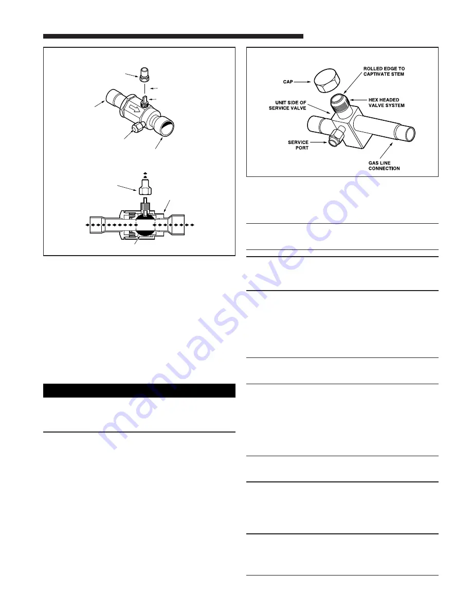
GAS LINE BALL SERVICE VALVE
5
CAP
1/4 TURN ONLY
COUNTERCLOCKWISE
FOR FULL OPEN
POSITION
VALVE STEM
GAS LINE CONNECTION
UNIT SIDE
OF VALVE
CAP
BODY
COOLING
CORE
PRESSURE TAP PORT
HEATING
GAS LINE SERVICE VALVE
6