


© 2012 Trane
18-BC56D1-5
Installer’s Guide
(INFORMATION APPLICABLE TO
ALL UNITS
)
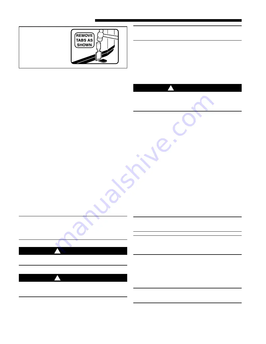
1. When removing unit from the pallet, notice the tabs on
the basepan. Remove tabs by cutting with a sharp tool as
shown in Figure 2.
2. The unit should be set on a level support pad at least as
large as the unit base pan, such as a concrete slab. If this
is not the application used please refer to application
bulletin SSC-APG001-EN.
3. The support pad must NOT be in direct contact with any
structure. Unit must be positioned a minimum of 12"
from any wall or surrounding shrubbery to insure
adequate airflow. Clearance must be provided in front of
control box (access panels) & any other side requiring
service access to meet National Electrical Code. Also,
the unit location must be far enough away from any
structure to prevent excess roof run-off water from
pouring directly on the unit. Do not locate unit(s) close
to bedroom(s).
4. The top discharge area must be unrestricted for at least
five (5) feet above the unit.
5. When the outdoor unit is mounted on a roof, be sure the
roof will support the unit’s weight. Properly selected
isolation is recommended to prevent sound or vibration
transmission to the building structure.
6. The maximum length of refrigerant lines from outdoor to
indoor unit should NOT exceed sixty (60) feet.
7. If outdoor unit is mounted above the air handler, maxi-
mum lift should not exceed sixty (60) feet (suction line).
If air handler is mounted above condensing unit, maxi-
mum lift should not exceed sixty (60) feet (liquid line).
NOTE:
Refer to “Refrigerant Piping Software” Pub. No. 32-3312-0*
(the position of the * denotes the latest revision number).
The outdoor unit must be properly matched to the indoor
unit. Refer to Application Bulletin # SCC-APG009-EN.
CAUTION
!
If using existing refrigerant lines make certain that all joints
are brazed, not soldered.
CAUTION
!
In scroll compressor applications, dome temperatures may
be hot. Do not touch top of compressor, may cause minor
to severe burning.
Final refrigerant charge adjustment is necessary.
Use
the Subcooling Charging procedure in the outdoor unit
Service Facts.
NOTE:
The refrigerant charge specified on the data plate is the
system charge plus 15 feet of rated line set.
C. SERVICE VALVE OPERATION
BRASS LIQUID AND GAS LINE SERVICE VALVES
The Brass Liquid and Gas Line Service Valves are factory
shipped in the seated position to hold factory nitrogen charge.
The pressure tap service port (when depressed) opens only to
the field brazing side of the valve when the valve is in the
seated position. The liquid line valve is
not
a back seating
valve (see
WARNING
below).
WARNING
!
Extreme caution should be exercised when opening the
Liquid Line Service Valve. Turn valve stem counterclock-
wise only until the stem contacts the rolled edge. (See
Figure 3) No torque is required.
BRASS GAS LINE BALL SERVICE VALVE
The Brass Gas Line Ball Service Valve is shipped in the
closed position to hold the factory nitrogen charge. The
pressure tap service port (when depressed) opens only to the
field brazing side when the valve is in the closed position. The
Gas Line Ball Service Valve is full open with a 1/4 turn. See
Figure 4.
BRAZING REFRIGERANT LINES
1. Before brazing, remove plugs from external copper stub
tubes. Clean internal and external surfaces of stub tubes
prior to brazing.
2. Cut and fit tubing, minimizing the use of sharp
90° bends.
3. Insulate the entire gas line and its fittings.
4. Do
NOT
allow uninsulated liquid line to come in direct
contact with bare gas line.
5. Precautions should be taken to avoid heat damage
to the pressure tap valve core during brazing. It is
recommended that the pressure tap port valve
core be removed and a wet rag wrapped around
the valve body.
NOTE:
Use care to make sure that no moisture enters pressure tap
port, while wet rag is being used.
NOTE:
Precautions should be taken to avoid heat damage to
basepan during brazing. It is recommended to keep the
flame directly off of the basepan.
6. Use a Dry Nitrogen Purge and Brazing Alloy without flux
when brazing the field line to the copper factory connec-
tion. Flow dry nitrogen into either valve pressure tap
port, thru the tubing and out the other port while brazing.
7. Braze using accepted good brazing techniques.
LEAK CHECK
IMPORTANT:
Replace pressure tap port valve core before attaching hoses for
evacuation.
After the brazing operation of refrigerant lines to both the
outdoor and indoor unit is completed, the field brazed
connections must be checked for leaks. Pressurize through
the service valve ports, the indoor unit and field refrigerant
BASEPAN TAB
REMOVAL
2


