


28
18-EB41D1-1A-EN
Before each heating season, the Flue Hood and
combustion blower should be inspected for signs of
any blockage or sooting. A
An
ny
y cclle
ea
an
niin
ng
g rre
eq
qu
uiirre
ed
d
ssh
ho
ou
ulld
d b
be
e p
pe
errffo
orrm
me
ed
d o
on
nlly
y b
by
y a
a q
qu
ua
alliiffiie
ed
d sse
errv
viicce
e
tte
ecch
hn
niicciia
an
n using the following procedure:
1. Turn the comfort control to OFF. Turn off power to
the unit. Turn the main power disconnect OFF. Turn
the manual gas valve OFF.
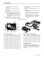
2. Remove the Flue Hood from the side panel.
3. Remove the combustion blower from the vestibule
panel. Disconnect blower wiring and pressure
switch hose.
4. Wipe blower and Flue Hood clean with a dry cloth.
5. Replace the combustion blower gasket with a new
one.
6. Reassemble combustion blower and Flue Hood in
reverse order of removal. Reconnect pressure
switch hose.
7. Verify all wiring is correct per the unit's wiring
diagram
8. Follow
“,”
procedure to place unit back in service.
Verify proper operation.
ECM Fan Motor Adjustments
E
EC
CM
M F
Fa
an
n M
Mo
otto
orr A
Ad
djju
ussttm
me
en
nttss
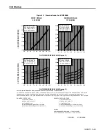
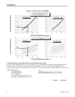
If the airflow needs to be increased or decreased, see
the Airflow Table in the SERVICE FACTS. Information
on changing the speed of the blower motor is in the
Blower Performance Table. Blower speed changes are
made on the ECM Fan Control mounted in the control
box. The ECM Fan Control controls the variable speed
motor. There is a bank of 8 dip switches, (See,
) located on the board. The dip switches work in
pairs to match the cooling/heat airflow (CFM/TON), Fan
off-delay options and electric heat airflow adjustment.
The unit ships with dip switches defaulted as shown in
.
Figure 8. ECM Fan Control
CFM
SELECTION
LIGHT
DIP
SWITCHES
S
Stta
attu
uss L
LE
ED
Dss
IIG
GN
N B
Bo
oa
arrd
d D
Diia
ag
gn
no
ossttiicc C
Co
od
de
ess
There are two LEDs on the IGN board that provide
status and diagnostic information. Refer to
for a description of the LED codes.
Table 17.
IGN LED Diagnostic Indicators
Status LED
Liteport LED
Steady OFF
Check Power or Failed Board
2 Flashes
System Lockout: Failed to detect or sustain
flame
Slow Flash Rate
Normal, No Call for Heat
3 Flashes
Pressure switch problem detected
Fast Flash Rate
Not used
4 Flashes
High Limit switch protection device open
Steady ON
Normal, No Call for Heat
5 Flashes
Flame sensed and gas valve not energized or
flame sensed and no “W” signal.
6 Flashes
Flame Rollout Switch open
7 Flashes
Thermostat miswired; W1 & W2
Fast Flash Rate:
The LED will flash on for 1/4 second and off for 1/4 second.
Slow Flash Rate:
The LED will flash on for 3/4 second, then off for 1/4 second.
The pause between groups of fast flashes is 3 seconds.


