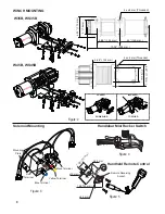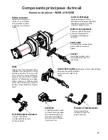
Winch Mounting:
1. To secure the winch, always use a flat, secure mounting location at least 3/16 inch (4.8 mm) thick.
2. 5/16-18 x 1 inch grade 5 hexagonal head cap screws and lock washer supplied with TrailFX
ATV/UTV Winch kit.
3. Torque mounting bolts to 12 lbs/ft (1.7 kg-m).
4. Attach roller fairlead / aluminium fairlead to winch mounting plate using 3/8-16 bolts, nuts and washers
5. Attach the clevis Hook to the rope.
6. Put the clutch in freespool position & manually feed cable loop through fairlead.
7. Attach hook to cable loop and re-engage the clutch.
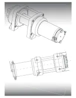
8. Refer to figure No. 2 for the mounting pattern & dimensions.
9. After mounting, rope should be in the under wind direction as shown in the figure 2. Over-winding
the rope may damage the winch and void warranty.
Solenoid Mounting:
1. The solenoid disconnects the winch from the power source (Battery) when ATV is not in use.
2. The solenoid should be mounted on a safe, clean place close enough to the battery.
3. The solenoid can be placed under the seats, in the rear storage box, or as recommended by the ATV
manufacturer.
4. The solenoid should have enough clearance from other metal parts of the ATV to avoid direct contact,
which may lead to solenoid malfunction.
5. Drill mounting holes for the solenoid, however do not mount the solenoid until you attach all the
cables from the battery, handlebar mini rocker switch & remote control.
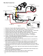
6. Cable colors should be matched with the contact terminal color codes (M+, M-, B+, B-) as shown in
the figure 3.
Handlebar Mini Rocker Switch Mounting:
1. Using the supplied black coated mounting clamp & screws, mount the mini rocker switch on the
handlebar.
2. A small piece of electrical tape could be used to avoid rotation of mini rocker switch cable after
mounting on the handlebar. (
N0TE
: It's recommended to mount this mini rocker switch on the left
side of the handlebar).
3. After mounting the mini rocker switch, route the cables to the place where the solenoid is
mounted. Connect the small red lead into the wire that electrifies with the ignition switch “ON”
and not electrifies with the ignition switch “OFF” as shown in the figure No 6. The wire
should only have power when the ATV/UTV key is in the “ON” position (Preferably fuse controlled).
Remote Control Socket Mounting:
1. Select a place to mount the remote control socket (female receiver).
2. Drill 3 holes as per the pattern & dimensions shown in the figure 5 and mount the socket.
3. After mounting the remote socket, route the cables to the place where the solenoid is mounted.
Connect the small red lead into the wire that electrifies with the ignition switch “ON”and not
electrifies with the ignition switch “OFF” as shown in the figure No 6. The wire should only
have power when the ATV/UTV key is in the “ON” position (Preferably fuse controlled).
4. Keep the remote socket closed with the built in cap when not in use.
9
English
Summary of Contents for W35B
Page 1: ...1 ATV UTV Winch Owner s Manual English Francais Espa ol...
Page 2: ...1...
Page 18: ...1...
Page 19: ...1 Treuil Manuel d utilisateur Francais...
Page 20: ...1...
Page 36: ...1...
Page 37: ...1 Winch de remolque Manual de usuario Espa ol...
Page 38: ...1...
Page 54: ...NOTES 54...
Page 55: ...1...


