background image

--------------------------------------------------------------------------------------------------------------

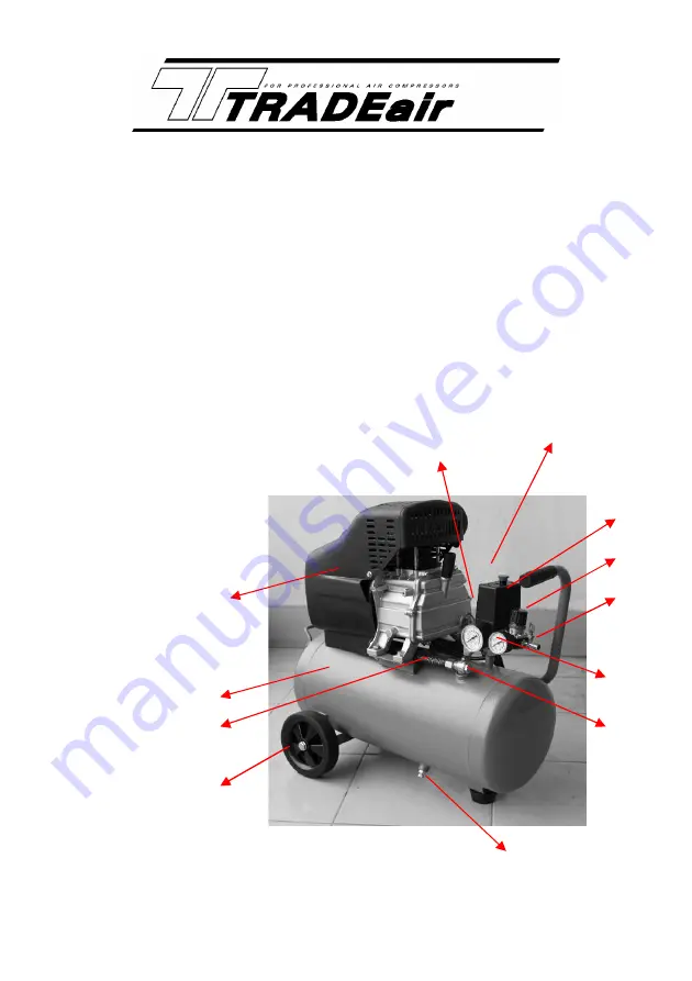
GENERAL VIEW AND MAIN COMPONENTS

1.

Main Compressor

2.

Pressure Switch

3.

Outlet Valve

4.

Pressure Regulator

5.

Pressure Gauge

6.

Non-Return Valve

7.

Drain Cock

8.

Wheel

9.

Discharge Pipe

10. Air Tank

11. Safety Valve

12. Fan Cover

Note:

Fittings may differ from those shown above.

11

2

4

3

5

6

7

8

9

10

12

1

Summary of Contents for MCFRC100

Page 1: ...DIRECT DRIVE COMPRESSORS MCFRC100 102A 103 108 109 107 113 MCFRC100 108 MCFRC102A 109 MCFRC103 MCFRC107 MCFRC113...

Page 2: ...ool to the Retailer is required together with the proof of purchase should be included with the returned product This warranty does not apply to damage that is determined to be from repairs made or at...

Page 3: ...or fire from combustible materials flammable liquids e g paint varnish petrol etc or flammable gases and dust of an explosive nature Guard Against Electric Shock Do not expose your compressor to rain...

Page 4: ...than those designed for use with compressed air could result in injury to the operator The output pressure of the compressor should be adjusted to the design pressure of the air tool or accessory bei...

Page 5: ...at is damaged should be properly repaired or replaced by an authorized service centre Disconnect Compressor Ensure that the compressor is disconnected from the mains supply and the tank is empty when...

Page 6: ...sor 2 Pressure Switch 3 Outlet Valve 4 Pressure Regulator 5 Pressure Gauge 6 Non Return Valve 7 Drain Cock 8 Wheel 9 Discharge Pipe 10 Air Tank 11 Safety Valve 12 Fan Cover Note Fittings may differ fr...

Page 7: ...topper 3 Air Filter 4 Oil Breather plug 5 A bottle of oil Fit the wheels to the unit using the axle kit provided and insert the rubber stopper into the spigot on the bottom of the tank Fit the air fil...

Page 8: ...il from the oil breather hole until the oil reaches the red mark on the sight glass Check that the small hole in the top of the breather pipe is clear and then insert it into the oil filler hole NOTE...

Page 9: ...the mains Start the compressor by pulling on the red knob Check for air leaks Note Output fittings may differ from those shown Warning Use the red knob to turn the unit on and off not the mains switc...

Page 10: ...that during use of the compressor the motor will cycle start and stop under the influence of the rising or falling pressure in the tank and the motor will start without any warning The maximum and min...

Page 11: ...Weekly 1 Remove air filter element and clean or replace as required Monthly 1 Inspect non return valve clean or replace as required Caution ensure that air the tank is empty for this operation 2 Manu...

Page 12: ...c and replace if necessary Excessive vibration or abnormal noise Connecting part loose Foreign body got into main compressor Piston knocking valve seat Moving parts seriously worn Check and retighten...

Page 13: ......

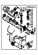
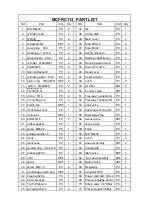
Page 14: ...4 Screw ST3 4 16 2 13B Piston Pin for MCFRC102A 109 103 1 45 Handle Grip 1 14 Circlip 12 2 46 One way valve 1 15A Connecting rod for MCFRC100 108 1 47 Bolt M8 25 4 15B Connecting rod for MCFRC102A 109...

Page 15: ......

Page 16: ...ut M8 PC 1 15 Piston PC 1 50 Air Filter PC 1 16 Hole Clip 12 PC 2 51 Handel Grip PC 1 17 Piston Pin PC 1 52 Discharge Pipe SET 1 18 Connect Rod PC 1 53 Bolt M8 30 PC 4 19 Oil Breather PC 1 54 Nut M8 P...

Page 17: ......

Page 18: ...ector A PC 1 16 connecting rod PC 2 52 Tree way connector B PC 1 17 breath pip SET 1 53 Leak valve PC 1 18 crankcase cover PC 1 54 right angle connector PC 1 19 oil leveler SET 1 55 Discharge Pipe PC...

Page 19: ...Distributed by L G Tool Machinery Distributors Limited 6 Kyalami Rd Westmead 3610 P O Box 15313 Westmead 3608 Telephone 031 7176800 Fax 031 7176868...

Reviews: