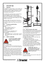
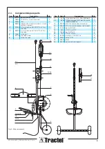
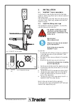
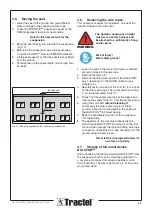
background image

8

Check the safety of the suspension 
structure at roof level and check 
that no counterweight has been 
removed (see PORTAFIX™ user 

manual).

Each anchor point of the 

suspension must be able to handle 
a minimum load of 10 kN. If a 
PORTAFIX™ or OMEGA is used, 
refer to the load table for WLL=400 
kg !

Make sure that the suspension 
is placed directly in line with the 
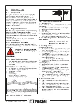
stirrup of the equipment (Fig. 10).

The operators must wear a hard hat 

if the site conditions require it.

Wear safety gloves !

It is recommended that access to 

the area at ground level below the 
seat and which may be in line with 
any object, tool or material falling 
from the equipment be prevented 
by being cordoned off.  This recom-
mendation becomes a requirement 
when the general public may have 

access to this area.

The equipment is intended for use 
in well lit areas either with natural or 

artificial light. Under artificial light 

the operator must have sufficient 

light.

Ensure that along the facade of the 
building there are no projections 
with which may collide the 

equipment.

When the work is completed, the 

competent person must have the 

seat taken out of service.

Danger

Danger

Danger

4.

OPERATING THE SEAT

4.1. 

Specific safety rules

Only wire rope specified by the 
TRACTEL Group should be used. 
It should be replaced if any of the 

defects indicated in chapter 6 are 

observed.

It is forbidden to use the seat 

without the fall arrest device 

BLOCFOR

.

The BLOCFOR™ fall arrest device 
is only efficient provided the upper 
safety hook (10) is secured to the 

suspension.

The fall arrest device will only fulfil 

its function if the safety wire rope 
between the suspension point and 

its anchor point on the seat support 
frame is taut.

Never work on the seat under 

severe wind or storm conditions 

(greater than 45 km/h)

The SUBITO seat is not designed to 

allow the operator to sit on it other 

than at ground level.

4.2.  Preliminary checks

Check that the working load on the 
equipment does not exceed the 

value indicated on the load plate 
secured to the stirrup.

Regularly check the correct 
operation of the SCAFOR hoist, 
the brake, and the fall arrest device 
BLOCFOR

.

Particularly check the anchorage 
and fixings of the suspension wire 
rope and of the BLOCFOR

 fall 

arrest device at two different anchor 

points. The collet of every safety 
hook (10/11) must be tightly screwed 
but not locked

Check the safety belt.

Danger

Danger

Danger

Warning

Warning

Warning

Warning

Warning

Warning

- MC1452-SUBITO_6FR-EN-D-IT-ES-NL  0

7

/201

8

Summary of Contents for subito

Page 1: ... MC1452 SUBITO_6FR EN D IT ES NL 07 2018 subito Temporary suspended seat TSS User and maintenance manual Equipment in accordance with European Union Directives and manufactured under ISO 9001 ...

Page 2: ... Preliminary checks 8 4 3 Maximum capacity permitted 9 4 4 Operation of SCAFOR 9 4 5 Moving the seat 10 4 6 Removing the wire ropes 10 4 7 Storage of fall arrest device BLOCFOR 10 5 Troubleshooting 11 6 Maintenance 12 6 1 Yearly check 12 6 2 Regular maintenance 12 7 Spare parts 13 7 1 SUBITO seat 13 7 2 SCAFOR hoist 13 7 3 Marking the equipment 13 Appendix CE declaration of conformity 14 Tractel S...

Page 3: ...not covered by this manual must be carried out by the manufacturer or an approved repairer Pay special attention to the suspension Make sure it corresponds to the applicable standards and recommendations Standard EN 1808 recommends a safety coeffi cient of 3 both as concerns anchor points and the stability of temporary beams The structure must be tested when commissio ned per EN 1808 a coefficient...

Page 4: ...wo jaws which grip the lifting wire rope at all times When the seat is moved up the jaws open sliding over the wire rope When the seat is moved down the jaws prevent all movement and the operator must manually keep the jaws open in order to perform this operation re chapter 4 4 Opera tion of SCAFOR The wire rope clamp end stop 7 prevents the seat from coming down beyond the length of the lifting w...

Page 5: ... m wire rope 1 6 10062 safety belt 1 7 29716 wire rope clamp 1 8 safety wire rope 1 Main components Fig 2 Pos Code Designation Qté 9 1 9428 lifting wire rope Ø 6 5 20 m with hook 1 9 2 6248 Lifting wire rope Ø 6 5 mm 30 m with hook on request 1 10 31652 M 10T connector top safety hook 1 11 31652 M 10T connector bottom safety hook 1 12 22516 bolt TH M10x50 3 13 8006 NYLOC nut M10 3 14 10426 bolt TH...

Page 6: ... lifting wire rope 9 correspond to the diameter shown on the SCAFORTM hoist technical plate the length of wire rope is sufficient for the applica tion and the end of the wire rope is as set out in fig 4 Avoid making loops when unreeling the wire rope Fig 5 Set the seat vertically under the suspension point 1 Pull the lifting wire rope hook side on to the roof 2 using a cord Fasten the hook to the ...

Page 7: ... mm from the guide tube Tighten the two locknuts Wind the unused length of wire rope on a reel 8 3 3 Fasten the safety wire rope Refer to the user manual for the BLOCFOR fall arrest device The operator on the ground must slowly pull the 1 rope A attached to the hook of the fall arrest device BLOCFORTM until the hook reaches him Fig 7 Warning never let go of the rope A during this operation Hold on...

Page 8: ... Danger Danger 4 OPERATING THE SEAT 4 1 Specific safety rules Only wire rope specified by the TRACTEL Group should be used It should be replaced if any of the defects indicated in chapter 6 are observed It is forbidden to use the seat without the fall arrest device BLOCFOR The BLOCFOR fall arrest device is only efficient provided the upper safety hook 10 is secured to the suspension The fall arres...

Page 9: ... it should automatically lock Operate both handles at the same time in the 5 same direction and symmetrically The left hand handle 20 automatically unlocks as 6 soon as it is released Restart the procedure described above to move up 7 again To move down Let go of the left hand handle 20 it will fall freely 1 to the bottom position and must remain there This handle must not be used when moving down...

Page 10: ...lifting wire rope from the SCAFOR 3 hoist operating it in the DOWN direction see chapter 4 4 Securely fasten one end of the cord A to the hook 4 of the safety wire rope Then unscrew the nut Fig 7 on the lower safety hook 11 Firmly hold the safety wire rope at the sleeve and 5 remove the safety hook 11 from the carrier stirrup Using the cord and 6 without releasing it accompany the safety wire rope...

Page 11: ...eturn the hoist to an approved automatically when the right hand repairer handle is in the low position On lifting the angle formed by the The brake lining is worn Return the hoist to an approved two handles is normally 180 repairer After many hours operation this angle reduces to 150 see Fig 11 Nothing happens if a sharp pull is Faulty internal overspeed Have the fall arrest device serviced appli...

Page 12: ...f the faults below is detected the wire rope must be replaced more than 12 broken wires over a 24 cm length damaged or deformed wire rope corrosion heat damage reduction of diameter of the suspension wire rope minimum diameter 5 9 mm Wire rope to be measured as shown in fig 14 6 2 3 Checking fall arrest device linked to the seat support Refer to the user manual for the BLOCFOR fall arrest device a...

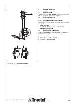
Page 13: ...ition to the part number and description please also quote model of hoist serial number engraved on side of hoist diameter of wire rope 7 3 Marking the equipment Check that all the labels and load plates are intact on the equipment Fig 15 A Technical plate with load table B SCAFOR technical plate Position of the labels and technical plates Fig 15 MC1452 SUBITO_6FR EN D IT ES NL 07 2018 ...

Page 14: ...8 TYP 760S 0100 06 10 confirming the conformity to the machinery directive No 2006 42 EC delivered by the notified body APAVE Italia Cpm Via Artigiani 63 I 25040 BIENNO BS Italy No 0398 The machine also complies with the following harmonized standards EN ISO 12100 1 1 A1 2 2 A1 EN 1808 A1 and with the other standards recommendations and following specifications DIN 15020 NOTE The suspension points...

Reviews: