Dynarope
HF 36/.
Révision 09
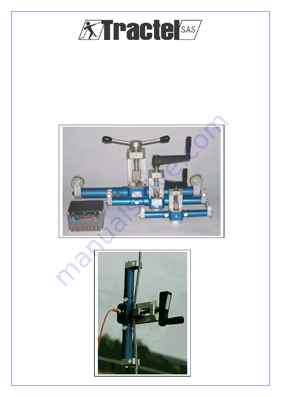
Operation and Maintenance Manual
29 RUE DU Progrès - 93107 MONTREUIL CEDEX - France
Tél. (1) 48.58.91.32 - Télex TRACTEL 230 020 - Adresse télégraphique TRACTELEV Montreuil - Télécopie (1) 48.58.19.95
Page 1: ...ope HF 36 Révision 09 Operation and Maintenance Manual 29 RUE DU Progrès 93107 MONTREUIL CEDEX France Tél 1 48 58 91 32 Télex TRACTEL 230 020 Adresse télégraphique TRACTELEV Montreuil Télécopie 1 48 58 19 95 ...
Page 2: ...must never be used to handle any loads exceeding the maximum utilization load indicated on the unit It must never be used in explosive atmospheres 8 This appliance should never be used for man riding applications without a thorough prior check that the utilization coefficients required for personnel safety have been applied and more generally that the safety regulations for the load line on which ...
Page 3: ...ode 5 Display HF 87 A 6 Calibration method 6 Correction abacus 7 Crank torque 7 3 Technical sheets HF 36 1 8 HF 36 2 9 HF 87 1 P 10 11 HF 87 A 12 4 Menus Synoptic 13 14 5 Users Manual Standard Mode 15 Record instruction 16 Calibration in Special Mode 17 Special Mode 18 6 Abbreviation explanation 19 20 7 Reference Codes HF 36 1 Frequency 21 HF 36 2 Frequency 22 HF 36 1 Analogue 23 HF 36 2 Analogue ...
Page 4: ...HF 36 strain gauges sensor and a digital display unit An analogue display units is available as an option and can be used under specific repetitive conditions The accessories are Lemo connection lead battery charger various leather protection boxes RS 232 connection lead and a recuperation data s software HF 36 1 leather box HF 87 1 P leather box ...
Page 5: ... on 2 3 6 7 8 12 11 10 9 1 2 3 50 10 100 RS232 POWER On Off S E F1 F2 F3 Shift T are CAPTEUR HF 8 7 P 1 HF 87 1 LED Display 2 Red dot 3 Vertical display 4 Power supply input 5 Load Cell input 6 RS 232 output 7 SHIFT button 8 F3 or Shift mode 9 F2 or Shift mode 10 F1 or E Shift mode 11 TARE or S Shift mode 12 On Off 4 5 6 8 11 10 9 12 7 Flashing while Shift mode Not available with tensiometer ...
Page 6: ...he Standard mode readout uses a data bank to correct the raw signal provided by the sensor Prior to a wire rope control you have to enter in the display the followings details via a simple to use menu Wire rope Diameter from 4 to 22 mm with a 1 mm increment Wire rope Structure Rigid rIgI Steel single strand Normal nor Steel multi strand Soft SoFt Kévlar et textile ropes When to use it Standard Mod...
Page 7: ... to render negligible the influence of placing the sensor on the cable Placing the sensor on the wire rope causes a shorting of the wire rope by approximately 1 5 mm To achieve increased accuracy measurement of wire rope not having those specifications may be carried out using the Special Mode Corrections The raw signal supplied by the sensor is digitalised and corrected by means of a formula corr...
Page 8: ...sert a dynamometer in the installation on the actual site and follow the user manual instruction See Calibration process in the Special Mode Calibration process 1 Fig 2 fixed end Wire rope Identical to the actual installation Length from 0 5 m to Tensioner Dynafor LLX Fixing end flexible or rigid according to the actual installation Working load Working load load cell incidence Adjust and memorise...
Page 9: ...commended as an economic solution for adjustment operations or load checks on wire rope used under specific repetitive conditions Aerial or most gay ropes of a single distribution network etc Calibration process Fig 2 Fixed end Wire rope Identical to the actual installation Length from 0 5 m to Tensioner Dynafor LLX Fixing end flexible or rigid according to the actual installation Working load Wor...
Page 10: ...r r o r i n d a N CRANK TORQUE There is no particular torque recommended to tighten up the crank onto the wire rope It s the wire rope angle that induce strain in the arms of the sensor The crank or the level is only used to induce the angle between the external support wheels and the stop block The HF 36 2 3 models are equipped with a rotary three level stop block the right position is indicated ...
Page 11: ...0 x 80 HF 36 2 43338 10 to 28 20 T 4 kg 500 x 280 x 90 HF 36 3 43358 20 to 44 40 T 8 kg 700 x 310 x 100 ASSOCIETED MATERIAL Digital Display HF 87 1 T Analogue Display HF 87 A APPLICATION This electronic load cell has been designed to measure the effort applied in a wire rope The resulting signal is used in a digital monitor controlled by a microprocessor which corrects the force information accord...
Page 12: ...n Special Mode SPEC 2 5 in Normal Mode NORM Barograph Indicates the updates from the sensor as a IDENTIFICATIONS The display corrects by calculation the information from the sensor taking in account the wire ropes diameter and specification Display HF 87 T 44098 3 m cable to connect to display 4 pin Lemo 75057 Transformer Charger 44108 Leather carrying case 44118 Input Signal Frequency from 500 Hz...
Page 13: ...erations to correct the raw measurement value Calibration is carried out under conditions identical to those found in actual situations For example the in line insertion of a dynamometer into the wire rope system to be checked the parameters specific to each calibration are recorded numbered registers When checks are made at some later date on the same wire rope system all that is required is to a...
Page 14: ... specific repetitive conditions Aerial or most guy ropes of a single distribution network etc TECHNICAL SPECIFICATIONS Display in force units to precise when you place the order Display 3 1 2 digit LCD 14 mm Display accuracy 1 of the target value Refer you to the correction abacus for the nearby values Calibration in factory following customer information Wire rope type Target tension IDENTIFICATI...
Page 15: ...de Press arrow display shows r 3 program version 36 2 selected sensor daN unit daN d 12 selected diameter Nor selected structure POS 1 position to select for the rotating plate pour HF 36 2 3 REMARK SHIFT permits to access to advanced functions While SHIFT mode is activated a dot flashes between 3rd and 4th digits E to enter S to exit E to enter E to valid Select with arrows automatic E to valid E...
Page 16: ...CTIC OF HF 87 1 P RECORD MENU see details page 15 E 4567 1 360 E GrAd SYNOPTIC OF HF 87 1 P ZERO MENU COdE E donE E 1 200 E Press Tare F1 during 3 seconds FrEE E E rEF 200 to FULL Precondition Sensor free of any load Press arrow Press SCHIFT Da N Da N ...
Page 17: ...StAn E Press E if at this moment the display is in Special mode SPEC goes to the standard mode StAn with the arrows 5 StAn E Press E 6 d I A E Press E Wire rope diameter 7 1 à 25 Ø Using the arrows select the correct diameter 8 10 E Press E to valid your choice 9 d I A Ø Using the arrows goes to the next step 10 S t r u Wire rope structure 11 S t r u E Press E 12 n o r Ø Select the correct structu...
Page 18: ... the arrows select the ambient temperature 8 22 E Valid with E 9 SPEd Ø Press E 10 0 à 99 Ø With the arrows select the wind speed 11 10 E Valid with E 12 dI r E Press E 13 1 à 360 Ø With the arrows select the wind direction 14 45 E Valid with E 15 rEC Press S to abort the record sequence 16 rEC E Valid with E 17 donE E Record operation done Press E to continue 18 FrEE Available memory 19 1 à 199 N...
Page 19: ...N non significant prior to calibration 4 7 4 0 E Press E 5 SPEC E Press E If the display indicate StAn using the arrow go first to the Special Mode SPEC 6 7 4 0 E Press E 7 n CAl Ø With the arrows select the parameter CALI 8 CALI E Valid CALI with E 9 n CAl E Valid n CAL with E 10 1 à 200 Ø Using the arrows select a N which will identified this calibration operation 11 3 E Valid the n CAL with E I...
Page 20: ...CTION EXPLANATION 1 36 1 36 2 36 3 Display is ready to analyse a HF 36 1 out put signal Or a HF 36 2 36 3 output signal 1 74 0 Readout in daN non significant prior to calibration 2 74 0 E Press E 3 SPEC E Press E If the display indicate StAn using the arrow go first to the Special Mode SPEC 4 n CAL E Valid n CAL with E 5 1 Ø Using the arrows select a calibration number corresponding with this spec...
Page 21: ...data d i a Wire rope diameter Da N Normal working readout daN da N adjust readout according with the standard dynamometer Dir Wind direction DonE Er 20 Record or delete completed Display does not receive any signal from the loadcell disconnected Lemo cable FrEE Available free memory GrAd Ambient temperature N o r normal wire rope Steel multi strands wire rope n C A L Calibration number r i G i rig...
Page 22: ...19 S t r u Wire rope structure Normal Rigid or Soft SpEd Wind speed Switch ON Turn display ON BAT Low battery Note ...
Page 23: ...gital kit HF 36 2 29818 Digital kit HF 36 3 36008 1 Loadcell HF 36 1 55268 2 Leather protection 1 55308 1 Loadcell HF 36 2 43338 2 Leather protection 2 55318 1 Loadcell HF 36 3 43358 2 Leather protection 3 44138 3 Digital display HF 87 T 44098 4 Leather box 44118 5 RS 232 lead 75067 6 Lemo 4 poles 75057 7 Software 75077 8 Charger 44108 Option specific calibration 122350 ...
Page 24: ...e kit HF 36 1 29788 Analogue kit HF 36 2 29798 1 Loadcell HF 36 1 45988 2 Leather protection 1 55308 1 Loadcell HF 36 2 55228 2 Leather protection 2 55318 3 Digital display HF 87 A 55288 4 Leather box 49358 6 Lemo 4 poles 75057 Option specific calibration 122350 ...