background image

13

g) Descent may be interrupted by firmly 

grasping the free end of the lifeline.

h)  Once the person has reached the ground, 

unfasten the person from the harness.

i)  Position the other end of the lifeline taut 

with no slack before attaching to the next 

person to descend.

j)  Ensure the derope

®

 descent device has 

properly cooled before its next use.

5.3 

Evacuation on a cableway descent

If it is not possible to evacuate the victim 

vertically due to an obstruction, the evacuation 

can be carried out down a cableway positioned 

at an angle between 30° and 60° (

Figure 13

).

a)  The rescuer secures two anchor slings to 

the structure. The higher anchorage to be 

used for the cableway and the lower point 

for the derope

®

 descent device.

b)  Attach the victim to the descent rope of the 

derope

®

 descent device and to the cable 

way using the 1 ft. (30 cm) lanyard.

c)  Two persons on the ground tension the 

cableway in the direction of travel to avoid 

any obstructions.

d) Release the descending rope from the 

jamming cleat and monitor the descent 

until the victim is on the ground.
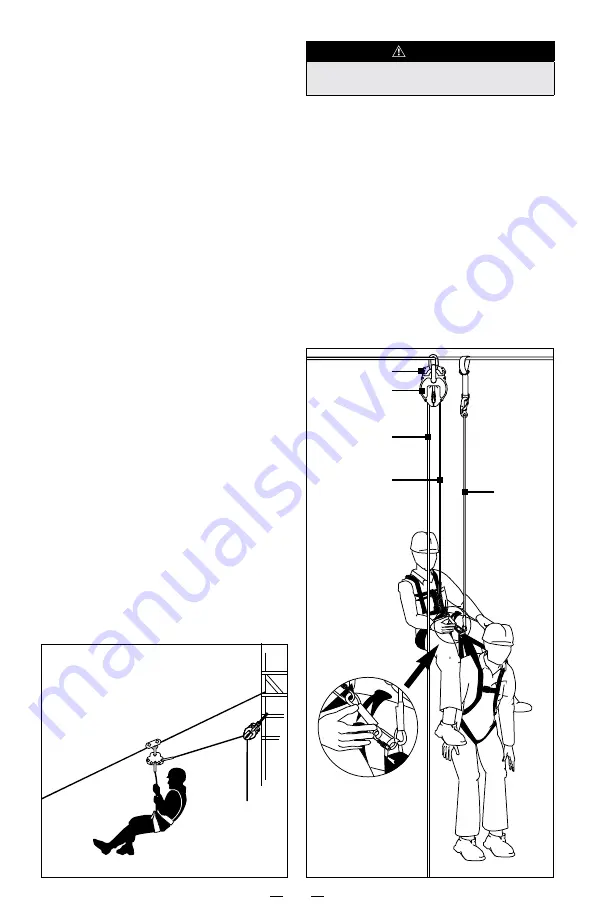
5.4 

Hoisting or lowering function

After the derope

®

 decent device has been 

properly secured above the victim as described 

in section 4, the self-locking snap hook at the 

extremity of the rope must be hooked into the 

frontal or back D-ring on the full body harness 

of the victim and secured.

5.4.1 

The rope between the device and the person to 

be lowered/hoisted must not have any slack; 

the free rope on the other side must be pulled 

downwards with force. The free end of the 

trailing rope is inserted in the aluminum pig tail 

so that it can be clamped in the jamming cleat.


WARNING

Ensure that the free end of the Kenmantle

®

 rope is 

inserted in the jamming cleat.

5.4.2  The handle is folded out from the handwheel 

and the handwheel is then rotated in the ‘UP’ 

or ‘DOWN” direction in order to hoist or lower 

the victim to a safe recovery platform or up to 

a point where the victim can be released from 

his fall protection sub-system.

5.4.3  The rope located in the jamming cleat must 

be kept tight during the hoisting of the victim 

with the hand crank in order to prevent an 

unintentional descend.

5.4.4 

Fold the handle back into the handwheel. Pull 

the rope located in the jamming cleat out of the 

jamming cleat and lower the victim.

Fig. 14

Pig tail

derope

®

Ascending end 

of the derope

®

Descending end 

of the derope

®

Lanyard

Fig. 13

30º to 60º

Summary of Contents for derope Up A

Page 1: ...derope emergency escape controlled descent devices use and maintenance instructions Meets or exceeds standards requirements established by ANSI Z359 4 07 CSA Z259 2 3 type 1E...

Page 2: ...d efficiency of operations that this manual be read and fully understood by the worker before using any fall arrest system ALL instructions contained herein must be carefully read and strictly followe...

Page 3: ...he use of the derope emergency escape controlled descent device must comply with applicable safety regulations either local state federal and regional and be compatible with one another and with the d...

Page 4: ...onsequences of dismantling or altering the derope emergency escape controlled descent device beyond description in this manual by anyone who is not authorised by Tractel Tractel declines any responsib...

Page 5: ...ope emergency escape controlled descent device beyond the information and description given in this manual IN CASE OF FALL ARREST xxix The rescue operation should not take more than 15 minutes Longer...

Page 6: ...n for a single user through the operation of the centrifugal brake 1 4 Features 1 4 1 Hoisting or lowering function This feature allows a victim to be lifted by the rescue worker with the help of the...

Page 7: ...k Carabiner Pig tail Pig tail Casing Fig 6 derope Up R Fastening pin Locking screw Rope blocking device Rope guide Safety pin Fig 4 derope Up A Hand wheel Folding handle Fig 5 derope Up E Adjustable l...

Page 8: ...scent height and number of repeated descents in accordance with the limits indicated in Table 2 below DANGER Following each use whether for a single descent or repeated descents the derope descent dev...

Page 9: ...netrate into the weave and dry causing the rope to become hard brittle and eventually break the fibers Solvents and drying agents within paint cause damage similar to chemical exposure 2 7 3 Exposure...

Page 10: ...STALLATION WARNING The derope descent device must only be installed and used by a trained person 4 1 derope T and derope Up A emergency escape controlled descent devices An inspection as per section 9...

Page 11: ...e tracpode tripod the latter must be equipped with a diverter pulley or two 2 pulleys if another piece of equipment is used on the same tracpode tripod e g blocfor self retracting lanyard or work winc...

Page 12: ...sistance during movement increases with the speed of movement WARNING Always use a self locking snap hook for an attachment in any personal rescue system 5 2 Evacuation function During a intentional v...

Page 13: ...the derope decent device has been properly secured above the victim as described in section 4 the self locking snap hook at the extremity of the rope must be hooked into the frontal or back D ring on...

Page 14: ...nsure the victim is properly connected to the extremity of the evacuation rope 5 5 5 Both persons can now evacuate by releasing the rope being held The descending speed will be controlled automaticall...

Page 15: ...15 Fig 15...

Page 16: ...s are apparent and are not described below remove the item from service replace it and contact Tractel for advice 9 2 1 If corrosive environments are unavoidable or the units are to be used for traini...

Page 17: ...quipment was sold to the original purchaser Return shipment must be prepaid 10 3 Any parts proved to be defective upon inspection by Tractel will be repaired or replaced at no cost 10 4 The obligation...

Page 18: ...t device model Lot number of the manufacturer Serial number of the manufacturer Owner User Date of purchase First use Date of inspection Inspection results details of identified defects Signature of c...

Page 19: ...Trainer User Evacuation height and weight of trainee Hoisting height and weight of trainee Trainer s signature Maximum number of repeated descents Descent height 165 ft 50 m 410 ft 125 m 650 ft 200 m...

Page 20: ...Drive Norwood MA 02062 Tel 781 401 3288 Fax 781 828 3642 LOS ANGELES 1 800 675 6727 tractel usa west tractel com 168 Mason way Unit B2 City of Industry CA 91746 Tel 626 937 6727 Fax 626 937 6730 UNITE...

Reviews: