


PTO Chipper Shredder
TWT/BIO100/0617
Page 7
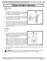
Preparing a New Chipper Shredder
After the Chipper Shredder is unpacked, the following
assembly may be required:
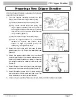
1. The rear support assembly includes the PTO
flange, drive shaft and a large double pulley.
(a) Remove protective tape from pulley rims.
(b) Slip v-belts around shaft and pulley, and
align support assembly with rear panel of
the Chipper Shredder. Hold loosely in position
with four 10 x 25 x 17mm hex head bolts and
wavy washers (figure 1).
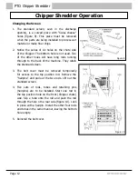
(c) Mount v-belts on large and small pulleys.
(d) Push to support bracket in a downward
direction to increase belt tension. Make
tension as tight as possible (nearly zero
deflection), and tighten the bolts.
2. Install the belt cover with two sets of wavy
washers and 8 x 16 x 13mm hex head bolts (see
figure 2).
3. Insert the castor wheel shafts into the wheel
mounts, and tighten the clamps. Adjustment to
level the Chipper-Shredder by raising or lowering
the wheels should be made at each work site
(figure 3).
4. Install Chipper chute with 8mm nuts and wavy
washers on the three mounting studs (figure 3).
5. Install Shredder hopper with 16 wavy washers
and eight sets of 8mm bolts and lock nuts. The
wavy washers go on both top and bottom.
6. Check out your assembly. Make sure all nuts, bolts and other fasteners are tight.
Figure 1
Figure 2
Figure 3