

Assembly Instructions | ILM Servo Kits
24
Edition 03/2021 EN
Assembly
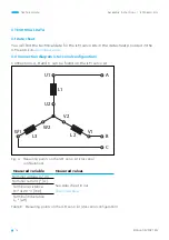
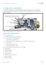
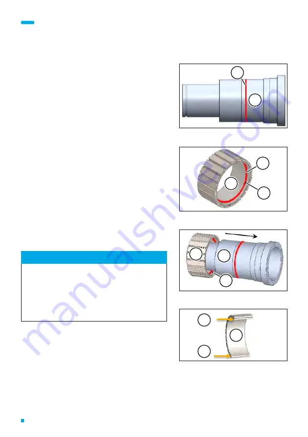
7.3.2 Rotor
►
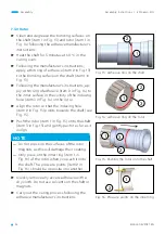
Clean and degrease the bonding surfaces on
the shaft (item 1 in Fig. 13) and rotor (item 1 in
Fig. 14) following the adhesive manufacturer’s
instructions.
►
Heat the shaft for 5 minutes at 60 °C in the
curing oven.
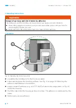
►
Following the manufacturer’s instructions,
apply a thin ring of adhesive (item 2 in Fig. 13)
to the bonding surface on the shaft (item 1 in
Fig. 13).
►
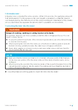
Following the manufacturer’s instructions, ap-
ply a thin ring of adhesive (item 2 in Fig. 14) to
the inner surface in the vicinity of the indexing
hole (item 3 in Fig. 14) on the rotor.
►
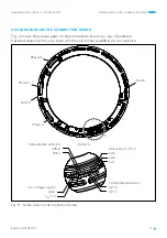
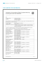
Align the rotor so that the indexing hole
(item 2 in Fig. 15) points towards the shaft (see
Fig. 15).
►
Push the rotor (item 1 in Fig. 15) onto the shaft
(item 3 in Fig. 15) and gently push it as far as it
will go.
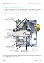
NOTE
—
Do not press on the surfaces of the rotor
magnets as this will damage their coating.
—
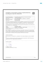
Only press on the inner ring (item 1 in
Fig. 16) of the rotor when you push it onto
the shaft. The pressure points (item 2 in
Fig. 16) should be opposite one another.
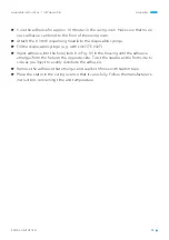
►
Quickly remove any excess adhesive with a
dry cloth. Do not use solvents on the shaft or
magnets.
►
Carry out the curing process following the
adhesive manufacturer’s instructions.
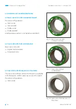
Fig. 13: Adhesive ring on the shaft
1
2
Fig. 14: Adhesive ring on the rotor
1
2
3
Fig. 15: Pushing the rotor onto the shaft
1
2
3
Fig. 16: Pressure points on the inner ring
1
2
2


