background image

BLUE M 


Model ESP400 Industrial Oven 

Page 23


8.1 Controller 

Features 

 
Temperature control is achieved with the Partlow Model 1160+ 
Controller. The 1160+ is a non-profiling type, 1/16 DIN controller with the 
following main features. The Type J thermocouple used for temperature 
sensing is placed in the airflow at the top of the workspace. 
 

ƒ

 Single 

Channel 

ƒ

  Selectable pre-tune, self-tune, manual tune 

ƒ

  1 Universal Input:  Type J Thermocouple 

ƒ

  1 Control Output:   0 - 10 VDC Time Proportioned 

ƒ

  2 Alarm Outputs:   Triac and Relay 

ƒ

  Communications:   Optional for RS-485 w/ Modbus 


Displays and Keys: 
 
The front panel of the Partlow 1160+ is provided with user-friendly features that aid in monitoring and setup. 
The upper display indicates actual process values while the lower display indicates setpoint value. The 
following LED indicating functions are employed. 
 

ƒ

  MAN:   On Steady – Indicates the Setup Mode has been entered 


Flashing – Indicates the Manual Mode has been entered 


ƒ

  AT: 

On Steady – Indicates the Controller Self Tune Mode is engaged 


Flashing – Indicates the Controller Pre-Tune Mode is engaged 


ƒ

  ALM:  Flashing – Indicates an alarm condition is present 


ƒ


  LED:  On Steady – Primary power is >0% 

 Flashes in unison with Time Proportioning Primary outputs, or for Current Proportioned outputs 
 

ƒ


  LED:  On Steady – Primary power is >0% 

Flashes in unison with Time Proportioning Secondary outputs, or for Current Proportioned 
outputs 

 
Raise and Lower Keys are provided, along with an Auto / Man Key. The Function Key (Circle Arrow) is used 
to navigate between modes and parameters. 


Data Communications:


As an option, RS-485 serial data communications may be provided with user-selectable Modbus protocol, or 
ASC II protocol (in some models). An RS-485 Communications Module is fitted in Option Slot A with this 
feature. RS-485 type communications is briefly described below. 
 
RS-485:   This interface uses only 2 wires. Both wires are used for transmitting and receiving data, and 
therefore, only one device may talk at a time. Up to 10 chambers may be connected to your computer on a 
multi-drop network up to 4,000 feet long. Data signals are measured as a plus or minus 5 Volt differential.  


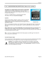
PARTLOW 1160+ 

8.0 

TEMPERATURE CONTROL - Partlow 1160+ Controller

Summary of Contents for BLUE M ESP400

Page 1: ...NUAL Model No ESP400 Serial No xxxxxxxxxx O N xxxxx Controller Partlow 1160 OVEN OPTIONS Process Timer Eagle Signal B856 24 Hr 7 Day Timer Grasslin FM1D Chart Recorder Alternate Controller Partlow 1166 2821 Old Route 15 New Columbia PA 17856 570 538 7200 Fax 570 538 7380 Rev 02 05 10 ...

Page 2: ...____ 11 5 3 Equipment Access Features _______________________________________________ 12 13 5 4 Exhaust Connection _______________________________________________________ 14 5 5 Power Supply Specifications and Connection ____________________________________ 15 16 5 6 Application of Power _______________________________________________________ 16 SYSTEMS and CONTROL 6 0 AIR CIRCULATION SYSTEM _____...

Page 3: ...__________________ 28 13 0 CHART RECORDER Optional ______________________________________________ 29 CHAMBER OPERATION MAINTENANCE 14 0 SEQUENCE of OPERATION ________________________________________________ 30 31 15 0 PREVENTATIVE MAINTENANCE ____________________________________________ 32 15 1 Maintenance Checks Procedures ____________________________________________ 32 34 15 2 Preventative Maint...

Page 4: ...onmental Lunaire Environmental Gruenberg Oven Blue M Lindberg Parts and service inquiries for equipment within each division should be directed to TPS by any of the following methods Important Please have the Model and Serial Numbers of your unit available when contacting us Model No Serial No Thermal Product Solutions PO Box 150 White Deer PA 17887 Thermal Product Solutions 2821 Old Route 15 New ...

Page 5: ...t may lead to poor performance and deterioration of unit 9 Make sure the chamber and any remote equipment provided are leveled when installed The chamber door may swing shut on personnel if unit is tilted 10 A main power disconnect is not provided with your unit We recommend that a fused disconnect switch on a separate branch circuit be installed as the power source in accordance with all National...

Page 6: ...ing it down Otherwise damage to the circulation motor shaft bearings will result 20 Do not modify any component on this unit Use only original equipment manufactured OEM parts as replacement parts Modifications to any component or the use of a non OEM replacement part could cause damage to your equipment personal injury or death INTERNATIONAL WARNING SAFETY SYMBOL DEFINITIONS Obey all DANGER WARNI...

Page 7: ...the additional suffix UL denotes that the unit is certified as UL Listed by Underwriters Laboratories Inc Special design concepts incorporated into these units are described where applicable 3 2 Specifications Temperature Range 15 C above ambient to 260 C 1 0 C after stabilization Workspace Capacity 2 8 cubic feet Run up Time to 260 C Empty chamber with intake exhaust closed 20 Minutes at 240 VAC ...

Page 8: ...on profiling type controller that features one universal type input and time proportioned control for heating Advanced communication display interface and configuration software improvements have been added to the 1160 Optional communications can be provided with RS 485 type serial communications 2 wire and user selectable Modbus or ASCII protocol Alternate Temperature Controller Partlow 1166 The ...

Page 9: ...temperature range of 5 C to 40 C max Maximum relative humidity 80 for temperatures up to 31 C decreasing linearly to 50 relative humidity at 40 C Supply voltage fluctuations do not exceed 10 of nominal voltage Overvoltage category II per UL 3101 Pollution category II in accordance with IEC 664 per UL 3101 Altitude up to 2000 m The listed chamber specifications are based on operation at 24 C ambien...

Page 10: ...l Equipment Vendor manuals will be supplied when the option is included Partlow 1166 Controller Manual Manual No 59129 2 Eagle Signal B856 Process Timer Manual Intermatic Grasslin FM1D Series 24Hr 7 Day Timer Manual Qty 2 Installation Programming Chart Recorder Manual Note Various other vendor manuals and product information sheets may be provided which contain important operation and maintenance ...

Page 11: ...A 86 Class B ovens are heat utilization equipment operating at approximately atmospheric pressure wherein there are no flammable volatiles or combustible material being heated in the oven Do not place the unit near combustible materials or hazardous fumes or vapors Do not locate unit in areas of wide ambient temperature variation such as near vents or outdoor entrances Do not install unit in a cor...

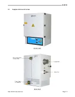
Page 12: ...BLUE M Model ESP400 Industrial Oven Page 12 5 3 Equipment Access Features FRONT RIGHT REAR RIGHT Thermocouple Wire Protector Plate Exhaust Port Intake Port Power Supply Junction Box ...

Page 13: ... base are shown below The unit is shown laying on its side Note Your equipment configuration may be slightly different from what is shown MACHINERY BASE ESP400 Left MACHINERY BASE ESP400 Right Power Supply Junction Box Heater Terminals TC Wires Circ Blower Motor Power Supply Cables ...

Page 14: ...poor temperature uniformity Never use an exhaust stack directly between the oven and the exhaust Vent ductwork should be run to a location outside of the building as necessary This should be done in accordance with all local code regulations Make sure all connections are secure Warning The exhaust port can become extremely hot Do not touch Avoid contact between the port and flammable materials Do ...

Page 15: ...sure and record the intended voltage source Note the measured value here 3 Reference the Line Voltage Min Max Tables below Verify that the power supply voltage source you measured and recorded is within the minimum and maximum allowable operating voltages for your chamber voltage rating If it is not within this operating range do not make the power connection Otherwise erratic operation and damage...

Page 16: ...nect your power supply cables to the labeled terminal blocks As an option a power cord and plug may be supplied with your unit Warning High Accessible Current An Earth connection is essential before connecting the power supply Make sure equipment is properly grounded in accordance with all codes 5 6 Application of Power Before energizing any equipment make a visual inspection for loose components ...

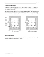
Page 17: ...or to cool down the oven after the heating cycle Basic Airflow Description Process air is heated as it is drawn in by the blower wheel and forced through open air electric wire elements The elements are configured in a cylindrical stack and are supported by ceramic discs Heated air is discharged up into the right side duct wall It then enters the workspace through perforations over the entire heig...

Page 18: ...irect airflow to both the top and bottom of the perforated duct wall The air intake damper is shown fully open The photo below includes the exhaust port along with the heater cover installed The air intake damper is shown fully open CONDITIONING PLENUM AIR CIRCULATION CONDITIONING PLENUM INTAKE DAMPER FULLY OPEN Air Intake Damper Fully Open Blower Wheel Intake Heater Stack Air Diffuser Panel Exhau...

Page 19: ... process An exhaust duct should be connected to the exhaust port and run to a location out of the building in accordance with all local safety codes 2 To promote faster drying times 3 When operating near ambient temperatures Air friction caused by the blower wheel circulating process air causes a rise in chamber temperature This can not be controlled by the temperature controller Both dampers shou...

Page 20: ... changing the setting Note The indented scale is marked for reference only There is no related unit of measure tied this scale Exhaust Damper The exhaust damper includes a lever attached to the damper shaft You must loosen the wingnut on the shaft assembly to open and close the butterfly damper An indented Open to Shut scale is marked with graduated lines on the assembly Make sure you tighten the ...

Page 21: ...into the right duct wall and into the workspace It flows horizontally across the workspace to condition the product and exits through the left duct wall Since the recirculation path is blocked by the intake damper 100 of all process air is forced out of the exhaust damper No air is recycled This system will permit fast drying times purge process vapors and allow near ambient operation Full Recircu...

Page 22: ...cylindrical stack and supported by ceramic disks The heater stack is isolated from the workspace so that no direct radiation can occur Heater wires extend through a ceramic plate and connect to terminals in the machinery base Heat Control The heat control circuitry is enabled through the High Limit Output of the Overtemperature Controller OTP A time proportioned output from the main temperature co...

Page 23: ...e Mode is engaged Flashing Indicates the Controller Pre Tune Mode is engaged ALM Flashing Indicates an alarm condition is present LED On Steady Primary power is 0 Flashes in unison with Time Proportioning Primary outputs or for Current Proportioned outputs LED On Steady Primary power is 0 Flashes in unison with Time Proportioning Secondary outputs or for Current Proportioned outputs Raise and Lowe...

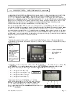
Page 24: ... keys until the desired setpoint is reached in the top display 3 Press the Function key to register the new setpoint The new Setpoint value will appear in the bottom display The current process value will return to the top display 8 3 Controller Parameter Setup The pre programmed controller configuration for your oven is documented in the Controller Parameter Setup Chart which is part of your Test...

Page 25: ...y one device may talk at a time Up to 10 chambers may be connected to your computer on a multi drop network up to 4 000 feet long Data signals are measured as a plus or minus 5 Volt differential 9 2 Temperature Control Temperature control with the Partlow 1166 is achieved with a 0 10 VDC time proportioned output Output 1 will energize a solid state relay which provides power to the heater stack Th...

Page 26: ...ll illuminate When conditions return to normal the EXCEED LED on the controller will turn off You must then press the RESET button on the controller The OUT LED will then turn off and Output 1 will close to permit the conditioning circuitry to reenergize The blower motor will start and the heat output of the main controller will be enabled through the Heater Contactor Note The 1161 is configured f...

Page 27: ...set pushbutton on the main control panel to reset the timer and begin a new process cycle The audible alarm will then turn off Time Setup This procedure explains how to set the process time using the factory set Hours Minutes configuration Since the timer is preset with an Off Delay sequence you do not need to make any changes with the Edit E or Program P keys The top display is the actual process...

Page 28: ...start the circulation blower and enable the heat control output Power to the heater is controlled by the main temperature controller When the programmed stop time is reached timer contacts will open to remove power from the circulation blower and heater The following features are included with the FM1D 24 Hour or 7 Day Programming 20 Programs with up to 10 On and 10 Off Events per day Manual 3 way...

Page 29: ... temperature measurement which is placed at the top of the workspace in the circulating process airstream The recorder is energized when the Start pushbutton is pressed on the main control panel The recorder configuration is documented in the Test Report which is located in the Supplemental Instructions Section For complete details on the operation of the recorder please reference the recorder s u...

Page 30: ...y 10 C 18 F above the rated operating temperature of the oven Note The Overtemperature Controller is configured for automatic reset during a power up condition only This includes the return of power after a power failure 6 If the optional process timer or 24 hour 7 day timer are employed set up your process cycle time or start stop time into the appropriate timer 7 Enter your temperature setpoint ...

Page 31: ...BLUE M Model ESP400 Industrial Oven Page 31 CONTROL PANEL ...

Page 32: ... with a high frequency use Therefore the preventative maintenance measures given here are offered as a guide allowing you to arrange your own program A Preventative Maintenance Schedule Log chart is provided at the end of this section The suggested inspection service dates given are for average use 15 1 Maintenance Checks Procedures Door Gasket Inspect your door gasket s for wear cracks tears etc ...

Page 33: ... temperature indicating accuracy and for the proper activation of limit or alarm outputs when provided Please reference the controller user manual for more information Inspection Period 1 Year Limit Controller Alarm Circuitry The Temperature Limit Controller should be checked for indicating accuracy and for proper activation of limit or alarm outputs A quick test is as follows 1 Set the OTP contro...

Page 34: ... tolerance established for the nameplate rating of your oven Inspection Period 6 Months Cleaning Important NEVER use a cleaning solution that contains chloride or flouride ions These ions are aggressive and highly corrosive and will attack stainless steel Thoroughly wash all surfaces with an appropriate cleaning solution Thoroughly rinse all surfaces ...

Page 35: ...ection Period Actual Date Inspected Serviced Actual Date Inspected Serviced Actual Date Inspected Serviced Actual Date Inspected Serviced Door Gasket 3 Months Door Sealing Quality 3 Months Chamber Interior Cleaning 3 Months Blower Wheel 6 Months Motor Shaft Seal 6 Months General Electrical Connections 6 Months Heater Electrical Connections 6 Months Main Temperature Controller Calibration 1 Year Li...

Page 36: ...BLUE M Model ESP400 Industrial Oven Page 36 SUPPLEMENTAL INSTRUCTIONS ...

Reviews: