background image

Form 9766      Rev.-   ECO 1-7322    9/17

To install the TO-SK-1 on the FSP-43 AND 

FSP-95 models: 

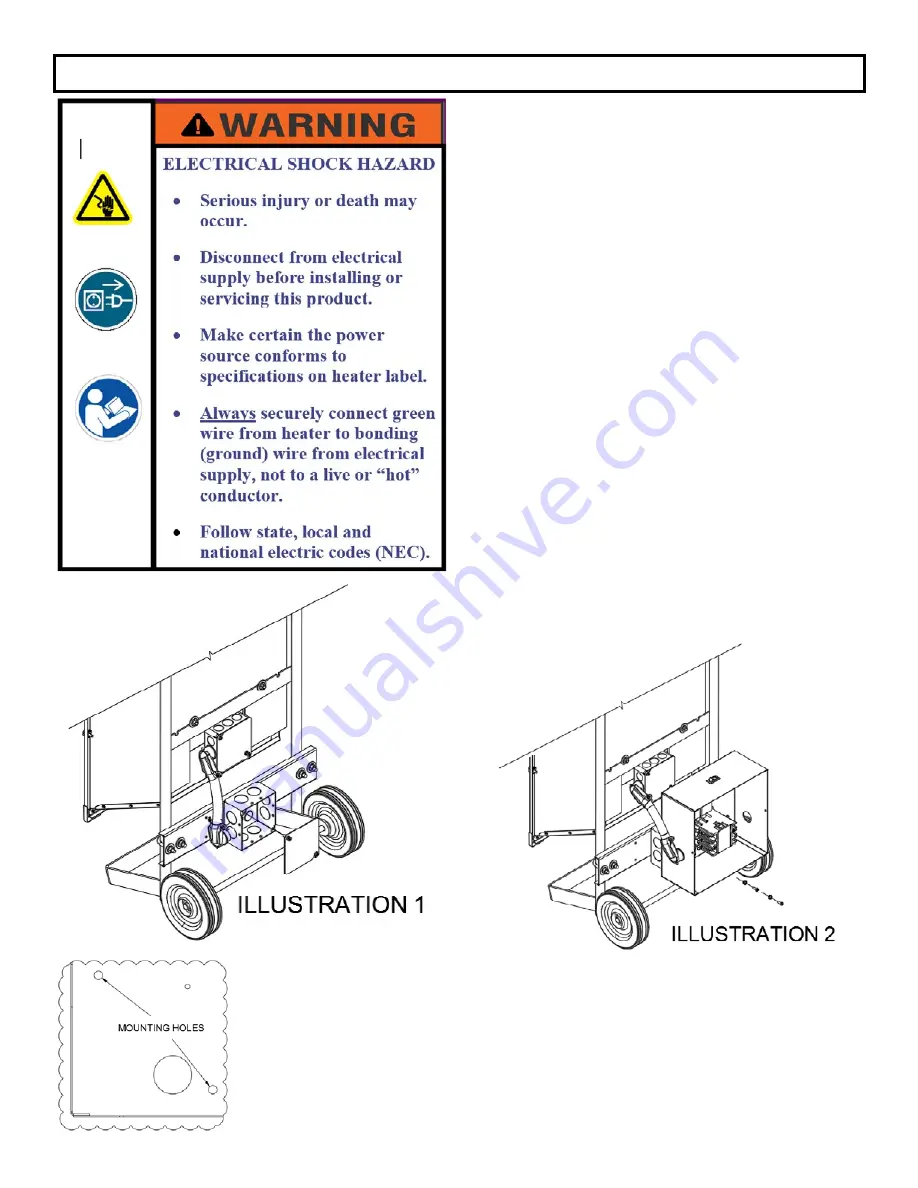
1.  Remove (2) screws and cover from bottom 4x4    

field  wiring  box.  Retain  the  screws.    Loosen 

conduit from bottom 4x4 field wiring box.  See 

illustration 1.

2.  Attach TO-SK-1 to the terminal box by removing 

screws and lid from TO-SK-1 enclosure, then 

attaching the TO-SK-1 to the 4x4 field wiring 

box.  Use the screws that were removed from 

the 4x4 wiring box and the two lockwashers 

supplied.  See illustrations 2 and 3.

3.  Re-attach the conduit to the TO-SK-1. 

4.  Wire the heater to the load side of the TO-SK-1   

contactor, see heater wiring diagram for single 

or  three phase connection. Connect designated 

transformer leadwire to pigtail on L1 of contactor 

(see Wiring Diagram A). See heater data label 

for correct line voltage.

5. 

Connect field wiring to line side of contactor.  

Secure ground wire to grounding lug.

6. Close and secure lid on enclosure.

7.  Connect to appropriate power source.

TO-SK-1 CONTROL BOX

INSTALLATION

3

Summary of Contents for fostoria FSP-43

Page 1: ...Form 9766 Rev ECO 1 7322 9 17 TO SK 1 Tip Over Switch Kit For FSP 43 AND FSP 95 REFER TO COMPLETE INDEX OF INFORMATION ON PAGE 2 TPI Corporation P O BOX 4973 JOHNSON CITY TN 37602 www tpicorp com ...

Page 2: ...rating Can be used in single and three phase applications The power switch illuminates when in use SPECIFICATIONS INDEX General Description Use Page 2 Specifications Page 2 Installation Page 3 Wire Wire Specifications Page 4 and 5 Signal Word Definitions DANGER Indicates an imminently hazardous situation which if not avoided will result in death or serious injury WARNING Indicates an imminently ha...

Page 3: ...at were removed from the 4x4 wiring box and the two lockwashers supplied See illustrations 2 and 3 3 Re attach the conduit to the TO SK 1 4 Wire the heater to the load side of the TO SK 1 contactor see heater wiring diagram for single or three phase connection Connect designated transformer leadwire to pigtail on L1 of contactor see Wiring Diagram A See heater data label for correct line voltage 5...

Page 4: ... GROUND GROUND FROM HEATER TRANSFORMER BLUE WHITE 12 3 LEADS TO HEATING ELEMENTS POWER SOURCE PRIMARY SIDE LEAD COLORS 600V GRAY 480V BLACK RED 277V BROWN 240V ORANGE 208V RED L3 L2 L1 CONTACTOR ROCKER SWITCH TIP OVER SWITCH TIP OVER SWITCH T3 T2 T1 4 1 2 3 4 FOR 3 OPERATION L1 1 4 L2 2 L3 3 FOR 1 OPERATION L1 1 3 L2 N 2 4 WIRING SCHEMATIC L1 L2 N FSP 4327 1 AND FSP 9527 1 MODELS FOR ALL OTHER MOD...

Page 5: ...804600 8 4 SO 08805100 14 4 SO 08804900 6 4 SO 03164001 12 3 SO 08804500 4 3 SO 08805300 12 4 SO 03164201 2 3 SO 08804700 10 3 SO 08804400 TABLE A Heater Model Kw Volts Amps Type SO Cable Size Plug Size 3 Ph Plug Size 1 Ph 3 PH 1 PH 3 PH 1 PH FSP 4320 3 4 3 208 11 94 20 67 12 4 10 3 20A 250V 4 WIRE 30A 250V 3 WIRE FSP 4324 3 4 3 240 10 36 17 91 14 3 12 3 20A 250V 4 WIRE 30A 250V 3 WIRE FSP 4327 1 ...

Reviews: