background image

12

ENGLISH

,

SECTION I:

INSTALLATION

GENERAL DESCRIPTION: The heater is designed to be installed in an outside wall so the full advantage of 
installation simplicity can be made with the “Flue Pipe”, which eliminates the need for tall chimney type flues. No 
hearth or fire surround is required.  

STANDARD INSTALLATION PARTS

The following standard installation parts are enclosed with heater. For alternate installation methods, you may 
need to purchase additional accessories which are available from your TOYOTOMI dealer. See “Accessory Parts”.

Drip Tray (1) (PART #17303814)

Pipe Stopper (1) (PART #17185278)

Wood Screw (3) (PART #172006066)

Truss Head Tapping Screw (2)

(PART #17160351) (Only for FQ-C70)

Flue Pipe (1) (PART #17224296)

Exhaust Air Cap (1) (PART #17212661)

Intake Air Cap (1) (PART #17212656)

Bent Joint (L) (1) (PART #17212598)

L-shaped Hose (2) (PART #17212598)

Inlet Hose (1) (PART #17212693)

Hose Band (2) (PART #17212677)

(Hose Clamp)

Ceramic log (3) (PART #17212505)

Log supporter (1) (PART #17303815)

Pipe Holder (1) (PART #17212685)

Canopy guard (1)

(PART #17303893) (for FQ-C70)

(PART #17303993) (for FQ-S70)

(FQ-C70)

Top guard assembly (1)

(PART #17303891) Only for FQ-C70

(FQ-C70)

Heat chamber lid (1) (PART #17212510)

(FQ-C70)

Tray (1)

(PART #17303825) Only for FQ-C70

(FQ-C70)

Handle for oven (1)

(PART #17303828) Only for FQ-C70

Wall Bracket (2 sets) (PART #17212589)
Bind Tapping Screw (2) (PART #17187555)
Wood Screw (2) (PART #17206066)

(1) (PART #17206066)

(Room temperature sensor)

Pan Head Tapping Screw (2) (PART #17208678)

Summary of Contents for FQ-C70

Page 1: ...FQ C70 FQ S70 GB OPERATING MANUAL PAGE 1 VENTED HEATING SYSTEM...

Page 2: ...on of water vapor 2 External tank to be purchased separately Consult your supplier for options SAFETY FEATURES Your heater is equipped with a number of integral safety features Please familiarize your...

Page 3: ...d physical sensory or mental capabilities or lack of experience and knowledge if they have been given supervision or instruction concerning use of the appliance in a safe way and understand the hazard...

Page 4: ...posits on burner and flue pipe Incomplete combustion Reduced heater life Use of a highly volatile flammable fuel such as gasoline can produce uncontrollable flames creating a severe fire hazard SECTIO...

Page 5: ...on the heater automatically at a preset time 6 SAVE key When the room exceeds the selected setting by approximately 2 C the heater will automatically shut off As the room temperature becomes lower tha...

Page 6: ...nected to the mains and not burning Use the adjustment keys to set the time First press either of the two keys to switch the CLOCK lamp and the information display will start blinking Next set the hou...

Page 7: ...ure is shown it also can continue to set altitude 3 Press the TIMER key and SAVE key at the same time for more than 3 seconds while the information display indicates You will hear the buzzer and will...

Page 8: ...rmation display will show the current time To clear the timer setting press the ON OFF button once NOTE The heater stops the operation and the heater will automatically start again by activating timer...

Page 9: ...HOW TO USE THE OVEN Set the tray as the accessory into the oven The inside temperature of the oven will vary depending on the operating mode of the heater When the heater operates in HIGH mode the in...

Page 10: ...small container under it c Loosen the two screws from the strainer cover and remove d Remove the strainer and wash with fuel e Return the strainer to its original position Replace strainer cover and...

Page 11: ...l yellow flickering in blue flame Normal lf rapid chugging sound from fuel pump does not cease and if heater shuts OFF 1 Push Fuel Sump Red Reset Button refer to SECTION E DO NOT hold down 2 Insure th...

Page 12: ...ain using a dry cloth e Cover heater completely with a large plastic bag to protect from dust 4 To store heater in another location a Disconnect heater b Close the main tank valve c Remove all fuel fr...

Page 13: ...172006066 Truss Head Tapping Screw 2 PART 17160351 Only for FQ C70 Flue Pipe 1 PART 17224296 Exhaust Air Cap 1 PART 17212661 Intake Air Cap 1 PART 17212656 Bent Joint L 1 PART 17212598 L shaped Hose 2...

Page 14: ...to be completed from outside 4 DO NOT install Flue Pipe where the air supply or exhaust gas outlet might become covered by snowdrifts fouled by outdoor debris or directly exposed to winds over 50 kph...

Page 15: ...500 m adjustments by authorized serviceperson is necessary Consult your supplier for advice 1 Select heater location Ensure minimum clearances as indicated below between heater and nearest combustible...

Page 16: ...canopy guard Remove the heat chamber lid from the heat exchanger Canopy guard Heat Chamber Lid Canopy Guard for both model b Gently insert the ceramic logs into three 3 brackets inside of burner prop...

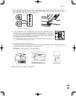
Page 17: ...ion wire is not touching the exhaust pipe The room temperature sensor can be installed with a wood screw Screw down the wood screw provided with the heater into the desired location on the wall Hook t...

Page 18: ...Rev 08 18 TOYOTOMI CO LTD 5 17 Momozono cho Mizuho ku Nagoya 467 0855 Japan http www toyotomi jp Printed in Japan 2273002060...

Reviews: