background image

1-5

1

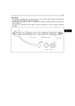
Cam shaft

• The camshaft is manufactured by knockdown system. The cam lobe and the com journal are pressed in

a hollow carbon steel tube. The cam lobe is welded.

• By adopting a special profile for the cam, together with improving inhalation efficiency, quiet operation

can be expected.

• The valve lift is optimized and the intake-air volume is heightened in order to improve combustion

efficiency.

Cam journal

Hollow carbon steel tube

Rotative 
direction

Exhaust

Intake

Cam lobe

Summary of Contents for 50-4FD100

Page 1: ...isagreement can take place between the descriptions in the manual and actual vehicles due to change in design and specifications Any change or modifications thereafter will be informed by Toyota Indus...

Page 2: ...NVERTER TRANSMISSION 2 PROPELLER SHAFT 3 FRONT AXLE DIFFERENTIAL 4 REAR AXLE 5 STEERING 6 BRAKE 7 BODY 8 MATERIAL HANDLING SYSTEM 9 MAST 10 CYLINDER 11 OIL PUMP 12 OIL CONTROL VALVE 13 HYDRAULIC PIPIN...

Page 3: ...LIST 0 10 SAFE LOAD FOR EACH WIRE ROPE SUSPENSION ANGLE 0 11 MEMBER WEIGHTS 0 11 ELECTRICAL PARTS INSPECTION 0 14 BOLT NUT TIGHTENING TORQUE 0 15 BOLT STRENGTH CLASS IDENTIFICATION METHOD AND TIGHTEN...

Page 4: ...0 2 0 VEHICLE EXTERIOR VIEWS HEADGUARD MODEL...

Page 5: ...0 3 0 1 2 3 4 5 6 7 8 9 10 11 12 13 14 15 16 17 18 19 20 21 CABIN MODEL...

Page 6: ...ton 50 4FD100 600 mm 23 6 in J08E UM 11 5 ton 50 4FD115 12 ton 50 4FD120 13 5 ton 50 4FD135 15 ton 50 4FDK150 16 ton 50 4FDK160 Vehicle model Punching format 50 4FD100 4FD120 50011 50 4FD115 50 4FD12...

Page 7: ...nt 2 3 Remove the gear Point Operations POINT 1 Disassembly Make match marks before removing the pump cover POINT 2 Inspection Measure the bushing inside diameter Limit 19 12 mm Operation to be explai...

Page 8: ...ters in operation procedure requiring special attention Standard Value showing the allowable range in inspection or adjustment Limit The maximum or minimum value allowed in inspection or adjustment AB...

Page 9: ...g a precision part such as the control valve use clean tools and operate in a clean location 5 Always follow the specified operation steps for disassembly inspection reassembly and adjustment 6 Always...

Page 10: ...ery dangerous Never under any circumstances put any part of the body including hands and feet under the jacked up vehicle Reference weight kg lb Vehicle model 50 4FD100 50 4FD115 50 4FD120 50 4FD135 5...

Page 11: ...Tilt the mast forward to raise the front of the vehicle 4 Support the flat spaces of the front axle mounting portion with stands HOISTING THE VEHICLE Always hoist the vehicle as specified in the spec...

Page 12: ...ression Suspension method Lifting angle Tension Com pression Suspension method 0 1 00 time 0 time 90 1 41 time 1 00 time 30 1 04 time 0 27 time 120 2 00 time 1 73 time 60 1 16 time 0 58 time 1 tf 2 t...

Page 13: ...3 13440 1 37 3021 11770 1 2 2646 9810 1 0 2205 27460 2 8 6174 26480 2 7 5954 23540 2 4 5292 19610 2 0 4410 12 5 mm 0 5 in 76880 7 84 17387 10980 1 12 2469 5 21570 2 2 4851 21280 2 1 4631 18630 1 9 419...

Page 14: ...100 6834 3940 8686 3940 8686 4000 157 2760 6085 2890 6371 2890 6371 3200 7055 4130 9105 4130 9105 4500 177 2930 6459 3070 6768 3070 6768 3360 7407 4280 9436 4280 9436 5000 197 3050 6724 3240 7143 3240...

Page 15: ...470 1036 470 1036 550 1213 550 1213 610 1345 1820 71 7 450 992 500 1102 500 1102 570 1257 570 1257 630 1389 2440 96 1 600 1323 670 1477 670 1477 730 1609 730 1609 810 1786 Member name Weight 50 4FD10...

Page 16: ...ly accurate reading is possible However it is difficult to observe operation or movement 1 Difference between results of measurement with analog and digital types The results of measurements using the...

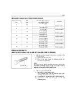
Page 17: ...ngth class from the table below 2 Judge the tightening torque for the hexagon flange bolt based on the threading diameter 3 The nut tightening torque can be judged from its corresponding bolt type BOL...

Page 18: ...59 91 137 65 160 330 600 930 1400 56 in lbf 12 24 43 67 101 6T 6 8 10 12 14 16 1 0 1 25 1 25 1 25 1 5 1 5 7 8 19 39 72 108 172 80 195 400 730 1100 1750 69 in lbf 14 29 53 80 127 7T 6 8 10 12 14 16 1...

Page 19: ...olts 1 Wash the bolt and threaded hole The threaded hole must be washed even when replacing the bolt with a new one 2 Completely dry the washed parts by blowing with air 3 Apply the specified seal loc...

Page 20: ...f cm ft lbf Hose inside diameter mm in Standard Tightening range 7 16 20UNF 25 250 18 1 24 to 26 240 to 270 17 4 to 19 5 6 0 24 9 16 18UNF 49 500 36 2 47 to 52 480 to 530 34 7 to 38 3 9 0 35 3 4 16UNF...

Page 21: ...r oil SAE90 Castle hypoid gear oil W 18 0 4 8 Planetary gears each of LH and RH Genuine Toyota hypoid gear oil SAE90 Castle hypoid gear oil W 1 7 0 45 Each chassis part Genuine Toyota MP grease Genuin...

Page 22: ...No 2 or equivalent J FGeneral lubricating oil SAE30 to 90 1 Lift bracket shaft 2 Lift roller pin Side roller pin 3 Tilt cylinder front pin 4 Planetary gear 5 Tilt cylinder rear pin 6 Torque converter...

Page 23: ...g knuckle Kingpin looseness T Cracks and deformation I Power steering Oil leak I Loosened mounting T Power steering hose replacement I Power steering rubber parts replacement I Steering synchro nizer...

Page 24: ...ir leak and oil leak I Air master rubber parts replacement I Brake fluid replacement I Disc brake Function wear and damage I Oil leak I Disc wear I Loosened mounting T Center brake drum and lining Loo...

Page 25: ...l leak and oil level I Differential oil replacement I Bolts and nuts looseness I Planetary gear Oil leak and oil level I Planetary gear oil replacement I ELECTRICAL SYSTEM Battery Fluid level I Fluid...

Page 26: ...earing wear and damage I Cylinder mounting loosening and damage I Lifting speed M Uneven movement I Oil pump Oil leak and abnormal sound I Drive gear wear I Hydraulic tank Oil level and contamination...

Page 27: ...n I Action I Rearview mirror Rear reflection on status I Dirt and damage I Instruments Action I Exhaust pipe and muffler Muffler rubber mount I Loosened or damaged mounting I Seat Seatbelt condition I...

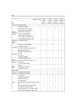
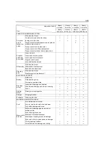
Page 28: ...1000 hours Every 2000 hours Engine oil Engine oil filter 1 Engine coolant 4 Air cleaner element Fuel filter Fuel hose 5 Torque converter transmission oil Torque converter transmission oil filter Torqu...

Page 29: ...ADJUSTMENT PROCEDURE 0 25 BLEEDING AIR FROM FUEL SYSTEM 0 26 ENGINE ASSY 0 27 REMOVAL INSTALLATION 0 27 RADIATOR ASSY 0 30 REMOVAL INSTALLATION 0 30 AIR CLEANER 0 31 AIR CLEANER CLEANING INSPECTION 0...

Page 30: ...1nn GENERAL Coolant INl Exhaust Earthl Supply pump Starter Air compressor Oil level gauge Closed ventilator Fuel filter EGR valve EGR cooler Coolant OUT Intake Aiternator Turbocharger Oil filter elem...

Page 31: ...piston in order to reduce noises Piston cooling jet system is used to cool down in order to maintain the appropriate temperature The structure with a cooling cavity ensures reliability for high press...

Page 32: ...lastic region where the change in the axial tension against the extension of the bolt is few This method has following characteristics Stable axial tension can be obtained Because fluctuation in the a...

Page 33: ...ube The cam lobe is welded By adopting a special profile for the cam together with improving inhalation efficiency quiet operation can be expected The valve lift is optimized and the intake air volume...

Page 34: ...EGR valve 1 linear solenoid EGR valve 1 drive signal Common rail pressure sensor 2 Common rail pressure sensor 1 Boost pressure sensor Engine speed sub sensor Engine speed main sensor Engine lift sen...

Page 35: ...y the EGR valve opening degree to adjust the oxygen density in the intake air that changes by EGR to the applicable target value for engine conditions engine speed supercharging pressure temperatures...

Page 36: ...s for pumping out linking to the intake pipe and the lower port is for intaking the blowby of the engine Also on the under side of the body there is a port to separate the oil mist included in the blo...

Page 37: ...n Oil supplied to the rocker arm shaft is distributed through the oil hole in the rocker arm shaft to each rocker arm bushing for lubrication and then goes through the oil hole in each locker arm to l...

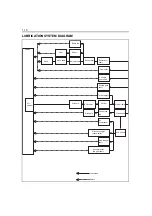
Page 38: ...Rocker arm shaft Cam shaft Cam idle gear shaft Sub idle gear shaft Turbo charger Main oil hole Oil filter Oil cooler Oil pump Piston pin Connecting rod Crank shaft Sub oil hole Air compressor Piston c...

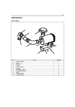
Page 39: ...PONENTS AIR CLEANER No Name Quantity 1 AIR CLEANER 1 2 CAP 1 3 BRACKET 1 4 HOSE 1 5 PIPE INTAKE 1 6 HOSE 1 7 WASHER PLATE 4 8 WASHER SPRING 4 9 BOLT 4 10 FLANGE BOLT 4 11 HOSE CLAMP 4 9 7 6 2 3 4 5 8...

Page 40: ...converter oil cooler Fan shroud Fan guard Cooling fan From pump From toruqe converter Cooler of brake cooling oil Propeller shaft For cooling fan drive To wet disk brake Brake cooling oil Torque conve...

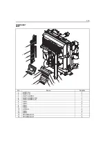
Page 41: ...Name Quantity 1 DUCT RH 1 2 DUCT LH 1 3 DUCT UNDER 1 4 DUCT UNDER RH 1 5 DUCT UNDER LH 1 6 SEAL 3 7 SEAL 2 8 SEAL 1 9 SEAL 1 10 SPONG 2 11 SEAL 2 12 SEAL 1 13 FRANGE BOLT 4 14 FRANGE BOLT 4 5 3 1 7 4...

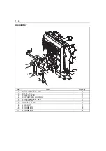
Page 42: ...antity 1 PULLEY BRACKET LWR 1 2 PLATE FAN 1 3 PULLEY COVER 1 4 SUPPORT FAN HOUSING 1 5 PULLEY BRACKET UPR 1 6 ADJUST BOLT 1 7 WASHER PLATE 2 8 LOCK NUT 1 9 FRANGE BOLT 8 10 FRANGE BOLT 2 11 FRANGE BOL...

Page 43: ...e cap 2 After fitting the cap apply the caulking to two locations No Name Quantity No Name Quantity 1 FLANGE BOLT 4 7 BEARING 1 2 BOSS 1 8 SNAP RING 1 3 OIL SEAL 1 9 BEARING 1 4 FAN 1 10 WASHER PLATE...

Page 44: ...1 16 FAN DRIVE No Name Quantity 1 OIL SEAL 1 2 BEARING 1 3 FAN PULLEY 1 4 BEARING 1 5 WASHER PLATE 1 6 SNAP RING 1 7 O RING 1 8 PULLEY COVER 1 5 3 1 7 4 2 6 8...

Page 45: ...1 FAN SHROUD UPR 1 2 FAN SHROUD RH 1 3 FAN SHROUD LH 1 4 FAN SHROUD LWR 1 5 PULLEY COVER 1 6 FAN SHROUD UPR 1 7 FAN GUARD 1 8 INSULATOR 2 9 SPACER 2 10 BOLT 2 11 SEAL 1 12 FLANGE BOLT 8 13 FLANGE BOLT...

Page 46: ...y sealing agent 08833 76002 71 on the set bolt threaded portion before reassembly 3 When breaking down the fan drive shaft put matching marks on When reassembling match the matching marks No Name Quan...

Page 47: ...HOSE INTERCOOLER OUTLET No 1 1 7 FLANGE TURBO OUTLET 1 8 WASHER CD SPRING 2 9 BOLT SOCKET 2 10 HOSE INTERCOOLER INLET No 1 1 11 PIPE 1 12 FLANGE BOLT 2 13 PLATE RH 1 14 PLATE LH 1 15 FLANGE BOLT 6 16...

Page 48: ...1 20 BRAKE COOLING OIL COOLER No Name Quantity 1 BRAKE COOLING OIL COOLER 1 2 HOSE 1 3 HOSE 1 4 FITTING 2 5 CLAMP 2 6 FLANGE BOLT 4 1 2 4 3 5 6...

Page 49: ...UE CONVERTER OIL COOLER 1 2 HOSE RADIATOR OUTLET 1 3 HOSE COOLER OUTLET 1 4 PIPE 1 5 HOSE 1 6 COOLER BRACKET LH 1 7 COOLER BRACKET RH 1 8 HOSE 1 9 HOSE 1 10 FITTING 2 11 CLAMP 2 12 FLANGE BOLT 4 13 FL...

Page 50: ...NUT FLANGE 2 11 BRACKET SUB ASSY EXHAUST PIPE 1 12 BOLT FLANGE 4 13 UPSWEPT EXHAUST 1 14 NUT FLANGE 7 15 STUD BOLT 1 16 MUFFLER SUB ASSY 1 17 PIPE SUB ASSY EXHAUST 1 18 PIPE SUB ASSY EXHAUST 1 19 CLA...

Page 51: ...1 11 BUSHING 2 12 ARM SUB ASSY ACCEL 1 13 ARM SUB ASSY SENSOR 1 14 BOLT FLAT HEAD SQUARE NECK 3 15 CUSHION 2 16 BOLT FLANGE 1 17 NUT FLANGE 3 18 BRACKET SUB ASSY ACCEL ARM 1 19 COVER SUB ASSY 1 20 SP...

Page 52: ...ts four 3 Adjust the tension of the V belt with a tension adjustment bolt 4 Tighten the fan fixing bolts four 5 Tighten the lock nut No 2 6 Measure the tension of the V belt Used SST 09216 76002 71 7...

Page 53: ...se connected to the fuel filter 2 Free the priming pump by rotating it counterclockwise 3 Apply a pressure by operating the priming pump up and down and bleed air by loosening the bleeder plug 4 Tight...

Page 54: ...inching piping 11 Disconnect the wiring from the torque converter 12 Sling the engine and torque converter with hoisting wires Point 2 13 Temporarily hoist the engine W torque converter and transmissi...

Page 55: ...ttery terminal Point Operations Point 1 Removal Installation Disconnect the piping to make the material handling pump as illustrated at left Point 2 Removal Installation Hoisting Caution Do not remove...

Page 56: ...Thank you very much for your reading Please Click Here Then Get More Information...

Reviews:

Related manuals for 50-4FD100