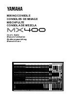
15. REMOVE CHAMBER WITH THROTTLE BODY
(a) Remove the union bolt holding the cold start injector
pipe to the chamber.
(b) Remove the bolts holding the No. 1 EGR pipe to the
chamber.
(c) Remove the bolts holding the manifold stay to the
chamber.
(d) Remove the four bolts, two nuts, bond strap and fuel
hose clamp.
(e) Remove the chamber with the throttle body, resona–
tor and gasket.
16. DISCONNECT FUEL RETURN HOSE
17. DISCONNECT FOLLOWING WIRES:
(a) Knock sensor wire
(b) Oil pressure sender gauge wire
(c) Starter wire (terminal 50)
(d) Transmission wires
(e) (with A/C)
Compressor wires
(f) Injector wires
(g) Engine coolant temp. sender gauge wire
(h) (A/T)
OD temp. switch wire
(i) Igniter wire
(j) VSV wires
(k) Start injector time switch wire
(l) Engine Coolant temp. sensor wire
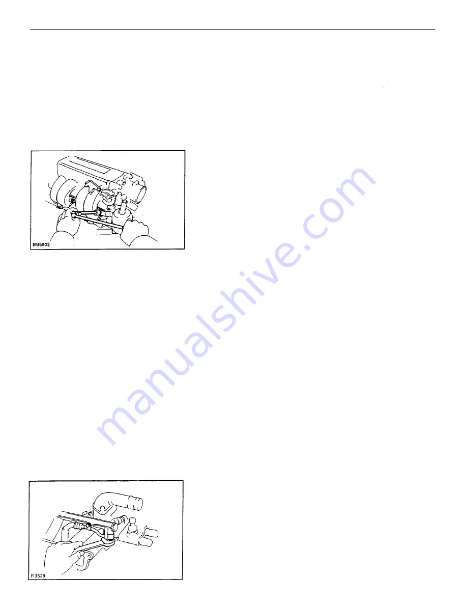
18. DISCONNECT FUEL HOSE FROM DELIVERY PIPE
Remove the bolt, union bolt and two gaskets.
19. DISCONNECT BY – PASS HOSE FROM INTAKE
MANIFOLD
20. (w/PS)
REMOVE PS BELT
13. REMOVE EGR VACUUM MODULATOR
14. DISCONNECT FOLLOWING WIRES:
(a) Cold start injector wire
(b) Throttle position wire
(c) (California only)
EGR gas temp. sensor wire
–
ENGINE
ENGINE MECHANICAL
EG1–17
Summary of Contents for 22R-E
Page 1: ...INTRODUCTION INTRODUCTION IN 1 ...
Page 9: ...VEHICLE LIFT AND SUPPORT LOCATIONS INTRODUCTION VEHICLE LIFT AND SUPPORT LOCATIONS IN 9 ...
Page 35: ...22R E ENGINE ENGINE EG1 1 ...
Page 45: ...HINT Adjust idle mixture as necessary ENGINE ENGINE MECHANICAL EG1 11 ...
Page 49: ...CYLINDER HEAD COMPONENTS ENGINE ENGINE MECHANICAL EG1 15 ...
Page 80: ...CYLINDER BLOCK COMPONENTS ENGINE ENGINE MECHANICAL EG1 46 ...
Page 110: ...EXHAUST SYSTEM COMPONENTS ENGINE ENGINE MECHANICAL EG1 76 ...
Page 116: ...LAYOUT AND SCHEMATIC DRAWING Federal and Canada ENGINE EMISSION CONTROL SYSTEMS EG1 82 ...
Page 117: ...LAYOUT AND SCHEMATIC DRAWING Calif ENGINE EMISSION CONTROL SYSTEMS EG1 83 ...
Page 118: ...POSITIVE CRANKCASE VENTILATION PCV SYSTEM ENGINE EMISSION CONTROL SYSTEMS EG1 84 ...
Page 126: ...EXHAUST GAS RECIRCULATION EGR SYSTEM Calif ENGINE EMISSION CONTROL SYSTEMS EG1 92 ...
Page 135: ...MFI SYSTEM DESCRIPTION ENGINE MFI SYSTEM EG1 101 ...
Page 211: ...FUEL PUMP ENGINE MFI SYSTEM EG1 177 ...
Page 226: ...FUEL TANK AND LINE COMPONENTS ENGINE MFI SYSTEM EG1 192 ...
Page 230: ...3 INSTALL INTAKE AIR CONNECTOR ENGINE MFI SYSTEM EG1 196 ...
Page 239: ...2 INSTALL THROTTLE BODY See page EG1 202 ELECTRONIC PARTS LOCATION ENGINE MFI SYSTEM EG1 205 ...
Page 278: ...3VZ E ENGINE ENGINE EG2 1 ...
Page 299: ... ENGINE ENGINE MECHANICAL EG2 22 ...
Page 300: ... ENGINE ENGINE MECHANICAL EG2 23 ...
Page 326: ...CYLINDER HEAD COMPONENTS ENGINE ENGINE MECHANICAL EG2 49 ...
Page 327: ... ENGINE ENGINE MECHANICAL EG2 50 ...
Page 367: ...CYLINDER BLOCK COMPONENTS ENGINE ENGINE MECHANICAL EG2 90 ...
Page 411: ...EXHAUST SYSTEM ENGINE ENGINE MECHANICAL EG2 134 ...
Page 419: ...LAYOUT AND SCHEMATIC DRAWING ENGINE EMISSION CONTROL SYSTEMS EG2 142 ...
Page 435: ...MFI SYSTEM SYSTEM CIRCUIT DESCRIPTION ENGINE MFI SYSTEM EG2 158 ...
Page 476: ... ENGINE MFI SYSTEM EG2 199 ...
Page 497: ...INJECTOR COMPONENTS FOR REMOVAL AND INSTALLATION ENGINE MFI SYSTEM EG2 220 ...
Page 508: ...FUEL TANK AND LINE COMPONENTS ENGINE MFI SYSTEM EG2 231 ...
Page 521: ...ELECTRONIC PARTS LOCATION ENGINE MFI SYSTEM EG2 244 ...
Page 569: ...IGNITION SYSTEM IGNITION SYSTEM IG 1 ...
Page 596: ...STARTING SYSTEM STARTING SYSTEM ST 1 ...
Page 597: ...STARTER COMPONENTS STARTING SYSTEM Starter ST 2 ...
Page 609: ...CHARGING SYSTEM CHARGING SYSTEM CH 1 ...
Page 613: ...GENERATOR COMPONENTS CHARGING SYSTEM Generator CH 5 ...