21
BUILD THE FUSELAGE
❏
2. Install your receiver battery in front of the receiver in the
same manner.
❏
3. Two pre-cut switch locations are provided on the
fuselage side. Choose the one that best matches your power
system choice. An external mounted charge jack could be
mounted below the switch. However, the canopy hatch is easily
removable for access to the receiver pack.
FINISH THE MODEL
❏
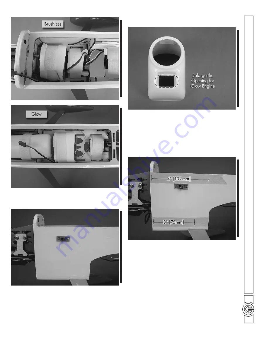
1. Before fi tting the cowl, make any cutouts necessary for
your power system. If you have installed a glow engine, a
cutout must be made for the exhaust, needle valve access, glow
plug access, and cool air exit. A rotary tool such as a Dremel
works very well for cutting holes in fi berglass. We also suggest
enlarging the air inlet with a glow engine installed to improve
air fl ow across the engine head.
❏
2. Put 5" [127mm] strips of masking tape on the sides
of the fuselage parallel to the fuse length (two per side) as
shown. Make a mark 1/8" [3.2mm] behind the front of the
fi rewall on each piece of tape. Use a ruler to accurately draw
a 4" [102mm] line from the mark onto the top pieces of tape
and a 3" [76mm] line on the bottom pieces. Make a mark at
the aft end of each line.


