Tower Hobbies KD58C Manual Download Page 7


Setting 3: Wheel Diameter Settings 

The “Set WD” setting is pre-set to the correct value for this eBike (26”). This cannot be adjusted. 

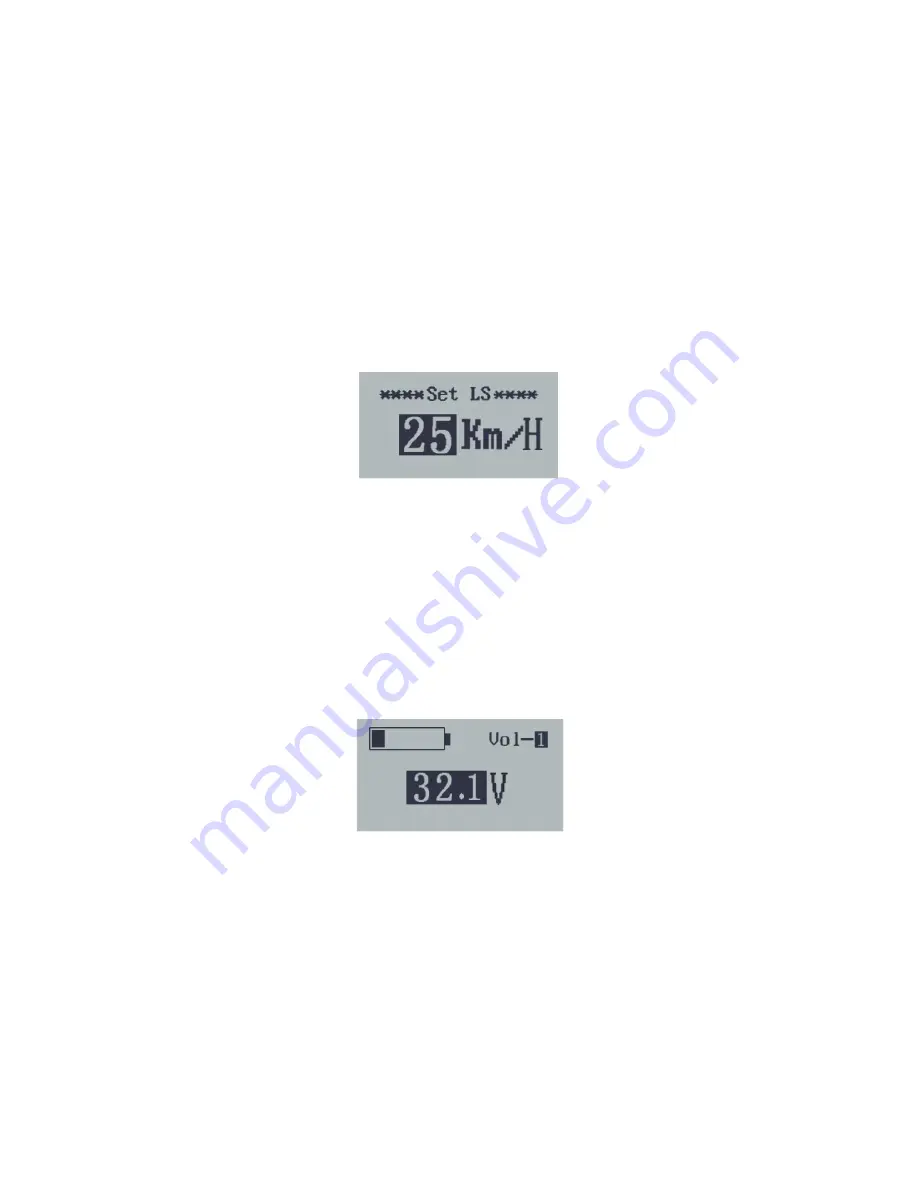
Setting 4: Speed Limit Settings 

Select “Set LS” to change the speed limit settings.  When running faster than the speed limit, 
the eBike power system will switch off automatically.  The speed limit range is 12km/h (7.5mph) 
to 40km/h (25mph).  The default value is 29km/h (18mph).   

To change this setting, press 

UP 

or 

DOWN 

to increase or decrease until the desired 

speed limit is displayed.  
Press 

MODE

 for 2s


to store the selection and return to the general selections interface.   


Setting 5: Battery Power Bar Settings 

Select “Set Voltage” to change the power battery display settings.   For example, VOL 1 is the 
voltage value at which the battery display will drop from two bars to one.  Voltage thresholds for 
each of the 5 battery bars must be entered one at a time.   

To set the voltage level for the first battery bar display, press 

UP 

or 

DOWN 


To store a changed setting and access the next bar’s threshold, press the 

MODE 

button.   

After the voltage value is entered for the fifth bar, hold MODE for 2s to confirm and 
return to the general settings interface.   

See 

Figure 3

 at the end of this manual for the default battery power bar settings. 


Advanced Settings 

The advanced settings are preset to recommended parameters, and shouldn’t need to be 
changed

.  Advanced settings can be used to adjust pedal assist power settings, slow start 

settings, backlight brightness and the start up password for the eBike.   
To access the advanced settings, hold the 

UP 

and 

DOWN 

buttons for 2s to enter general 

settings. Enter “

1 2 3 4

” when prompted for a password, then hold the 

UP 

and 

DOWN 

buttons 

for 2 more seconds to enter the advanced settings interface. Press the 

UP 

or 

DOWN 

button to 

transition through the available settings, then press the 

MODE 

button to adjust the selected 

setting.   

Summary of Contents for KD58C

Page 1: ...paddleboard Pin terest com towerpb Twitter towerpb 2 year limited warranty E L E C T R I C B I K E S TOWER KD58C ElectrIC BICYCLE INTELLIGENT DISPLAY MANUAL 1 YEAR LIMITED WARRANTY TOWERELECTRICBIKES COM Tower Electric Bikes 1253 Garnet Ave San Diego CA 92109 866 622 4477 TOWER LIFE ...

Page 2: ... Indicator 5 Power Code Identification 5 General Settings 5 Trip Distance Reset 5 Unit Selection 5 Wheel Diameter Settings 6 Speed Limit Setting 6 Battery Power Bar Settings 6 Advanced Settings 6 Power Set 7 Current Setting 7 Assistance Number 7 Speed Sensor 7 Slow Start Up 7 Backlight Brightness 8 Start Up Password 8 Additional Settings Operations 8 Recover Default Settings 8 Appendix 9 Default P...

Page 3: ...rage temperature 30 70 Appearance and Size Size 56x46mm Function Summary and Button Definition Function Summary This LCD controller is capable of the following functions Smart battery indicator Assistance level indication Speed indication incl running speed max speed and average speed Motor output indicator Trip time indication Trip distance and total distance The push assistance function Headligh...

Page 4: ...controller Display Layout General Operation Turning the eBike On Off To turn on the eBike system hold the MODE button for 2 s Perform the same function to turn the eBike system off When the eBike system is turned off the leakage current is less than 1 uA When parking the eBike for more than 10 minutes the eBike system switches off automatically Display Interface After turning on the eBike system t...

Page 5: ...N button is released Push assistance function should only be used when pushing the eBike Switching the Lighting On Off To switch on the eBike headlight hold the UP button for 2s To switch off the eBike headlight perform the same function hold the UP button for 2s Pedal Assistance Level Selection Assistance levels indicate the output power of the motor The default value is level 1 The default power...

Page 6: ...ttings menu the controller will ask for a password THE DEFAULT PASSWORD IS 1 2 3 4 This can be entered by using the UP arrows to change each digit of the combination followed by the MODE button to move to the next digit of the combination Setting 1 Trip Distance Reset Clear Trip is used to reset the trip distance Press the UP or DOWN button to choose YES or NO to clear the trip distance The defaul...

Page 7: ...ry bars must be entered one at a time To set the voltage level for the first battery bar display press UP or DOWN To store a changed setting and access the next bar s threshold press the MODE button After the voltage value is entered for the fifth bar hold MODE for 2s to confirm and return to the general settings interface See Figure 3 at the end of this manual for the default battery power bar se...

Page 8: ...ettings interface Please see Figure 4 at the end of this manual for available pedal assist level ranges Advanced Setting 2 Current Setting The current setting is pre set to the correct value for this eBike 20A This cannot be adjusted Advanced Setting 3 Assistance Number The current setting is pre set to the correct value for this eBike n 12 This cannot be adjusted Advanced Setting 4 Speed Sensor T...

Page 9: ...d select enable and press MODE to confirm the selection Enter the new start up password P3 XXXX using the UP and DOWN buttons Press MODE to confirm the selection and return to the advanced settings menu Follow the same steps to disable the startup password Note that the P2 password will no longer be the default value of 1212 Additional Settings Operations To exit the settings menu hold the DOWN bu...

Page 10: ... 4 75 5 96 Figure 2 Error Code Definitions Error Code Definition 21 Current Abnormality 22 Throttle Abnormality 23 Motor Abnormality 24 Motor Hall Abnormality 25 Brake Abnormality 30 Communication Abnormality Figure 3 Default Power Bar Settings Power Bar Level Voltage 1 40 0V 2 44 5V 3 46 5V 4 47 5V 5 Full 49V 9 ...

Page 11: ...Assist Power Table Figure 5 Connection Layout Display side Connector Display side Adapter Switch Wiring Figure 6 Line Sequence Table Line Sequence Color Function 1 Red VCC 2 Blue K Lock 3 Black GND 4 Green RX RX 5 Yellow TX TX 10 ...

Reviews: