background image

7


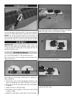
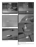
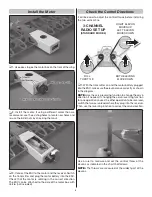
12. Use a piece of masking tape to hold the elevon 

in position.


13. Mark the pushrod.


14. Make an L-bend at the mark.


15. Attach the clevis in the 4th hole of the control horn. 

Secure the L-bend to the servo arm with a Faslink.


16. Install the pushrod and control horn on the 

second elevon.


17. Mount the receiver in the front of the servo compartment 

with Velcro (not included). Secure the antennas following the 

manufacturer’s recommendations.

Summary of Contents for CrazE Wing EP ARF

Page 1: ...f the final user assembled product By the act of using the user assembled product the user accepts all resulting liability If the buyer is not prepared to accept the liability associated with the use of this product the buyer is advised to return this kit immediately in new and unused condition to the place of purchase To make a warranty claim send the defective part or item to Hobby Services at t...

Page 2: ...bs across the country Contact the AMA at the address or toll free phone number that follows Academy of Model Aeronautics 5151 East Memorial Drive Muncie IN 47302 9252 Tele 800 435 9262 Fax 765 741 0057 Or via the Internet at www modelaircraft org IMPORTANT Two of the most important things you can do to preserve the radio controlled aircraft hobby are to avoid flying near full scale aircraft and av...

Page 3: ...ision Servo OR 2 FUTM0034 Futaba S3102 Aircraft Micro Metal Gear Servo TOWG2000 Tower Hobbies Electric Motor 30 35 1000 FLZA6612 Flyzone 40A Select Scale ESC FLZA6614 Flyzone Prop Adapter GPMQ4480 1 x 6 Velcro Propellers 3S LiPo APCQ4118 9x6E or APCQ4119 9x7 5E 4S LiPo APCQ4116 8x8E Battery and Charger A 3S to 4S 1800mAh 2200mAh LiPo battery is required to power the CrazE Wing ARF ElectriFly 3S 18...

Page 4: ...ly contact Order Assistance Order Assistance Ph 800 637 6050 Fax 217 398 7721 E maiI airsupport towerhobbies com CONTENTS 1 2 3 3 Hardware not shown 2 Large nylon control horn 2 Nylon control horn back plate 2 Nylon clevis 2 Nylon Faslink 2 Silicone clevis keeper 2 2 56 x 6 152 mm wire pushrod 4 Hardwood servo mounting blocks 4 2 56 x 3 8 9 5mm Machine Screw 4 2 x 3 8 9 5mm Sheet Metal Screw 4 3 x...

Page 5: ...ll the Servos 1 Install the grommets in the two aileron servos 2 Cut the two servo arm gauges from the back of this instruction manual 3 Follow your transmitter instructions for setting up a delta wing plane a Connect the servos to the appropriate channels on the receiver and temporarily connect the ESC to the receiver b Switch on the transmitter and connect the motor battery to the ESC c Center t...

Page 6: ...6 7 Install the servo hatch 8 Install the nylon clevis 9 Attach the clevis 10 Install the control horn 11 Cut out the reflex gauge from the back of this instruction manual ...

Page 7: ...5 Attach the clevis in the 4th hole of the control horn Secure the L bend to the servo arm with a Faslink 16 Install the pushrod and control horn on the second elevon 17 Mount the receiver in the front of the servo compartment with Velcro not included Secure the antennas following the manufacturer s recommendations ...

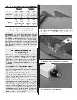
Page 8: ... before installing the two vertical fins FULL THROTTLE BOTH ELEVONS MOVE DOWN 3 CHANNEL RADIO SET UP STANDARD MODE 2 RIGHT ELEVON MOVES UP LEFT ELEVON MOVES DOWN 1 With the transmitter on and the motor battery plugged into the ESC make sure the elevons move correctly as shown in the diagram NOTE Use the servo reversing function to change the servo direction if needed If changing the servo reversin...

Page 9: ...ansmitter is switched off before the motor battery is disconnected the motor could come on Review the instructions included with your radio system for setting the failsafe Setting the Tactic TR625 receiver failsafe 1 Switch on the transmitter and connect the motor battery to the ESC 2 Make sure the throttle stick is down 3 Press and hold the Link button on the receiver until the red LED goes out a...

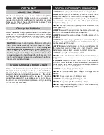
Page 10: ...ng water from under the decal Apply the rest of the decals the same way Check the C G Center of Gravity DO NOT OVERLOOK THIS IMPORTANT PRCEDURE A model that is not properly balanced will be unstable and possibly unflyable The CG is 1 1 4 31mm to 1 7 8 47mm from leading edge 1 Mark the C G range on the top of the motor box 2 With the plane ready to fly motor battery installed use a Great Planes C G...

Page 11: ...connections or broken wires corroded wires or connectors or try relocating the receiver and antennas ELECTRIC MOTOR SAFETY PRECAUTIONS ALWAYS Wear safety glasses whenever running motors ALWAYS Keep your face and body as well as all spectators away from the plane of rotation of the turning propeller ALWAYS Keep loose clothing and objects such as pencils or screwdrivers that may fall out of a shirt ...

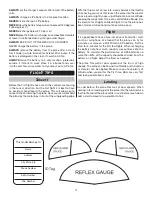
Page 12: ...advance the throttle while having your assistant launch the plane into the wind at a nose level or slightly nose up attitude Gain some altitude keeping the wings level Once at a comfortable altitude trim the elevons for straight and level flight Once the plane has been trimmed future hand launches will be easy Flight It is a good idea to have a timer set on your transmitter wrist watch or cell pho...

Reviews: