


BD4603
9
TLGS625
ASSEMBL
Y INSTR
UCTIONS
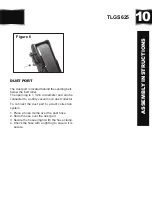
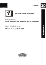
The tool rest attaches to the inward side of
the guard and provides a surface that must
be used to support the workpiece during
operation. Certain types of grinding/sanding
may require jigs or accessories that will be
used with the tool rests to assure the proper
angle of the workpiece against the wheel.
Failure to install and use the tool rest can lead
to serious personal injury.
To install the tool rests:
1.Loosely attach the tool rests perpendicular
to the belt or wheel surface with the knob
bolts, 5 mm washers and hex nuts.
2.To adjust the angle of the sanding belt
tool rest, use a square or a protractor to
set the angle of the tool rest in relation
to the sanding belt.
3.Adjust both tool rests approximately 1/16
to 1/8 in. from the grinding wheel and the
sanding belt and tighten the knob bolts.
(
in Fig. 3
)
shows the correct adjustment
for the tool rest at the grinding wheel.
INSTALLATION TOOL RESTS
Figure 3
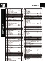
The spark guard must be installed and posi-
tioned 1/8 in. from the grinding wheel to minimize
sparks flying towards the operator. The eye
shield must be positioned between the grinding
wheel and the operator's face to protect the
operator from flying debris. This is not a rep-
lacement for safety glasses!
To install the spark guard and eye shield:
1.Using the included 5 mm screw and washer,
install the spark guard as shown
(
in Fig. 4
)
.
SPARK GUARD & EYE SHIELD
2. Attach the eye shield to the support bracket
with the included 6 mm carriage bolt and hex
nut. Use the 8 mm hex bolt and washer to attach
the support bracket to the grinder.
Figure 4
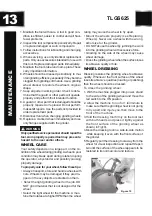
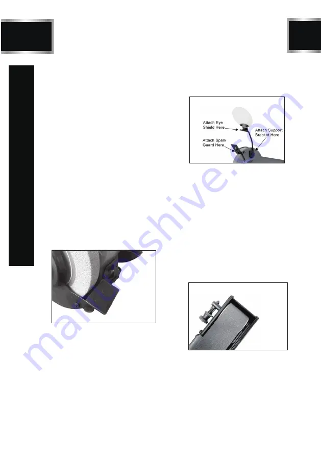
BELT TRACKING
Tracking the sanding belt means to center the
belt on its rollers, so that it runs balanced and
does not make contact with the sides of the
belt cover.
To track the sanding belt:
1. Disconnect the machine from the power
supply.
2. Rotate the grinding wheel.
3. As you rotate the grinding wheel, watch how
the sanding belt rides on the upper roller. If
the belt is tracking properly, the sanding belt
should be centered between the sides of the
belt cover as shown (in Fig. 5).
4. While spinning the wheel, turn the tracking
control knob counterclockwise to make the
belt move to the left, or turn the tracking
control knob clockwise to make the belt move
to the right (in Fig. 6).
5. After the belt is centered, spin the grinding
wheel approximately ten times to ensure
that the belt continues to track properly.
Figure 5
Summary of Contents for TLGS625
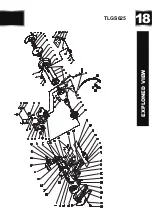
Page 18: ...18 EXPLONED VIEW TLGS625...