background image

C E I L I N G

W

A

L

L

100 cm

100 cm

Ÿ

Use a 9 kg LPG cylinder only. 

Ÿ

The hose must comply with the requirements of SANS 1156-2 or BS 2312.

Ÿ

A dented, rusted or damaged LPG cylinder may be hazardous and should not be used.

Ÿ

Never use a cylinder with a damaged valve connection.

Ÿ

The cylinder valve must have a horizomtal outlet with a G5/8 left hand thread to suit the regulator.

Ÿ

Never connect the cylinder directly to the heater. A regulator must always be used.

Ÿ

The regulator must comply with the requirements of SANS 1237 and must have a G3/8 right hand threaded 
connector.

Ÿ

Make sure the rubber seal on the regulator connector is in place and in good condition before connecting 
the regulator to the cylinder valve.

Ÿ

The heater is for outdoor use only. Always ensure that adequate fresh 
air ventilation is provided.

Ÿ

Always maintain proper clearance to combustible materials, i.e. top 
100 cm and sides 100 cm minimum.

Ÿ

The heater must be placed on firm level ground

Ÿ

Never operate heater in areas where petrol or other flammable liquids 
or vapours are stored.

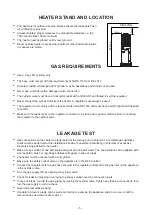
HEATER STAND AND LOCATION

GAS REQUIREMENTS

LEAKAGE TEST

Ÿ

Gas connections on the heater are leak tested at the factory prior to shipment. A complete gas tightness 
check must be performed at the installation site due to possible mishandling in shipment or excessive 
pressure being applied to the heater. 

Ÿ

Make a soap solution of one part liquid detergent and one part water. The soap solution can be applied with 
a spray bottle, brush or rag. Soap bubbles will appear in case of a leak.

Ÿ

The heater must be checked with a full cylinder.

Ÿ

Make sure the safety control valve on the appliance is in the OFF position.

Ÿ

Connect the regulator with the gas hose secured to the regulator outlet and to the gas inlet on the appliance 
to the cylinder valve. 

Ÿ

Turn the gas supply ON by opening the cylinder valve.

Ÿ

Check for leaks by brushing or spraying the soapy solution over the connection joints

Ÿ

In case of a leak, turn off the gas supply by closing the cylinder valve. Tighten any leaking connections, then 
turn the gas supply on and re-check.

Ÿ

Never leak test while smoking.

Ÿ

If unable to prevent a leak, call a service technician to examine the appliance and do not use it until the 
technician has declared it safe to do so

- 5 -

Summary of Contents for 16/DK1027

Page 1: ...ING HAZARDOUS FIRE OR EXPLOSION MAY RESULT IF INSTRUCTIONS ARE IGNORED It is the consumer s responsibility to see that the heater is properly assembled installed and taken care of Failure to follow in...

Page 2: ...turned o until it has cooled down Do not paint the radiant screen control panel or top canopy re ector The control compartment burner and circulation air passageways must be kept clean Frequent cleani...

Page 3: ...OF CONTENTS Caution 1 Heater Stand and Location 2 Gas Requirements 2 Leakage Test 2 Operation and Storage 3 Cleaning and Care 4 Parts and Specifications 4 Assembly Parts and Procedures 6 Problems Chec...

Page 4: ...otective device removed for servicing the heater must be replaced before operating the heater Adults and children should stay away from high temperature surface to avoid burns or clothing ignition Chi...

Page 5: ...ours are stored HEATER STAND AND LOCATION GAS REQUIREMENTS LEAKAGE TEST Gas connections on the heater are leak tested at the factory prior to shipment A complete gas tightness check must be performed...

Page 6: ...he pilot burner ignites If the pilot burner does not ignite repeat Step 3 4 After the Pilot Burner ignites turn the appliance control valve to the full position and leave it at that setting for 5 minu...

Page 7: ...corrosive Remove debris from the burner to keep it clean and safe for use Cover the burner unit with the optional protective cover when the heater is not in use PARTS AND SPECIFICATIONS 1360 mm 880 m...

Page 8: ...M8 X 15 Qty 2 AA M8 Flange nut Qty 2 Burner assembly N O I T P I R C S E D T R A P QUANTITY A Flame screen guard 1 B 1 Cylinder Housing C 1 D Base E Wheel 1 1 Philips screwdriver with medium blade Sp...

Page 9: ...bracket with wheel to the base 2 Use 4 pcs M5x8mm screws nuts to join the cylinder housing to the base ASSEMBLY PROCEDURES C CC AA BB x 2 M8 x 15 mm Bolts M8 Flange Nut x 2 FF Wrench x 1 Hardware Used...

Page 10: ...8mm screw to join the burner head and cylinder housing body 4 Use the M6 Dome Nut to connect the two half safety guards to the burner head Hardware Used CC EE x 4 x 1 Philips screwdriver Screw M5 X 8...

Page 11: ...re that the rubber seal on the end of the regulator is in place and is in good condition The cylinder valve thread is a left hand thread and the regulator handwheel must be turned in an anti clockwise...

Page 12: ...ace Thermocouple Burner will not light Pilot light assembly bent or not in correct location Place pilot light in correct position and retry PROBABLE CAUSE 12 Distributed by D K Gas Appliances PO Box 3...

Reviews: