background image

27

Technical Information

Service Manual

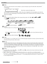
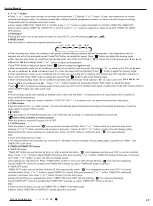
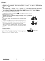
Emergency operation 

switch

Panel

Sketch map for 

replacing batteries

Note:

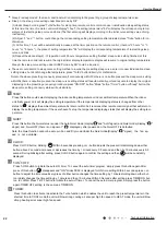
If “H1” is displayed on the remote controller while it’s not operated by the professional person/after-sales person, it belongs to the misoperation. 

Please operate it as below to cancel it.Under the OFF status of remote controller, hold the “MODE” button  and “X-FAN” buttons simultaneously

for 5s to cancel “H1” display.

● If remote controller displays “H1”, it belongs to the normal function reminder. If the unit is defrosting under heating mode, it operates according 

to H1 defrosting mode. “H1” won’t be displayed on the panel of indoor unit;

● Once you set H1 mode, if you turn off unit by remote controller, H1 will display 3 times on the remote controller and then disappear;

● Also, when you set  H1 mode, when you change to heating mode, H1 will display 3 times on the remote controller and then disappear. 

Summary of Contents for TM09HEDI

Page 1: ...Service Manual ...

Page 2: ...emote Controller Introduction off YAA1FB1F 20 6 2 Remote Controller Introduction off YT1FF MOTO 24 6 3 Brief Description of Modes and Functions 28 Part Ⅱ Installation and Maintenance 31 7 Notes for Installation and Maintenance 31 8 Installation 34 9 Maintenance 48 9 1 Trouble Table 48 9 3 Maintenance Method for Normal Malfunction 54 10 Exploded View and Parts List 56 11 Removal Procedure 72 Append...

Page 3: ...18HEDI CV010N01100_L81561 4 TM12HKDI CN51000060_L81561 5 TM18HKDI CN51000070_L81561 6 TM24HKDI CN51000080_L81561 7 TM09HFDI CN210N0070_L81561 8 TM12HFDI CN210N0060_L81561 9 TM18HFDI CN210N0080_L81561 10 TM24HFDI CN210N0100_L81561 11 TM09HTDI CN610N0060_L81561 12 TM12HTDI CN610N0070_L81561 13 TM18HTDI CN610N0050_L81561 14 TM24HTDI CN610N0080_L81561 TM24HKDI YT1FF MOTO YT1FF MOTO TM09HTDI TM12HTDI T...

Page 4: ...r Power Output W 30 30 30 Fan motor running current A 0 14 0 14 0 14 Evaporator Material Aluminum Fin copper Tube Aluminum Fin copper Tube Aluminum Fin copper Tube Evaporator Pipe Diameter mm Φ7 Φ7 Φ7 Evaporator Number of Rows 2 2 2 Evaporator Fin Pitch mm 1 3 1 3 1 3 Evaporator Length L X Height H X Width W mm 511X396X24 511X396X24 511X396X24 Motor Model FN30F ZL FN30F ZL FN30F ZL Overload Protec...

Page 5: ...0 43 Fan Motor Speed rpm 845 700 600 515 845 700 600 515 620 570 520 280 Fan Motor Power Output W 11 11 50 Fan Motor Power Input W 50 50 100 Fan motor running current A 0 23 0 23 0 43 Fan Motor Capacitor μF 1 1 3 Gas Pipe to indoor unit mm Φ9 52 Φ12 Φ16 Liquid pipe mm Φ6 35 Φ6 Φ9 52 Connection method Flare Connection Flare Connection Flare Connection Drain Connection outer diameter mm 31 31 31 Dim...

Page 6: ... 5 0 28 Fan Motor Speed rpm 1000 920 780 720 1160 985 800 680 1230 970 760 640 Fan Motor Power Output W 75 22 5 40 Fan Motor Power Input W 100 124 80 Fan motor running current A 0 43 0 54 0 35 Fan Motor Capacitor μF 3 3 1 5 Gas Pipe to indoor unit mm Φ12 7 Φ15 9 Φ9 52 Liquid pipe mm Φ6 Φ9 52 Φ6 Connection method Flare Connection Flare Connection Flare Connection Drain Connection outer diameter mm ...

Page 7: ... 5 0 3 Fan Motor Speed rpm 1160 30 985 30 800 35 680 35 1160 30 985 30 800 35 680 35 790 30 690 30 610 40 480 40 Fan Motor Power Output W 40 20 15 Fan Motor Power Input W 145 110 55 Fan motor running current A 0 63 0 56 0 28 Fan Motor Capacitor μF 3 2 5 1 Gas Pipe to indoor unit mm Φ16 Φ12 Φ9 52 Liquid pipe mm Φ9 52 Φ6 Φ6 Connection method Flare Connection Flare Connection Flare Connection Drain C...

Page 8: ...ifugal Motor Full Load Amp FLA A 0 3 0 3 Fan Motor Speed rpm 1130 960 830 700 690 610 480 Fan Motor Power Output W 49 15 Fan Motor Power Input W 80 55 Fan motor running current A 0 35 0 28 Fan Motor Capacitor μF 3 1 Gas Pipe to indoor unit mm Φ9 52 Φ9 52 Liquid pipe mm Φ6 Φ6 Connection method Flare Connection Flare Connection Drain Connection outer diameter mm 26 17 Dimension of Outline WXDXH mm 7...

Page 9: ...ia Curve Tables for Both Models Duct Type 0 Middle Low High 20 30 50 60 Noice dB A 40 24K 18K 12K 09K Cassette 0 Middle Low High 20 30 50 60 Noice dB A 40 12 18K Compact Panel 24K Floor ceiling type 0 Middle Low High 20 30 50 60 Noice dB A 40 09 12K 18K 24K ...

Page 10: ...8 Technical Information Service Manual 0 Middle Low High 20 30 50 60 Noice dB A 40 09K 12K 18K Console ...

Page 11: ...9 Technical Information Service Manual 3 Outline Dimension Diagram ...

Page 12: ...10 Technical Information Service Manual ...

Page 13: ...11 Technical Information Service Manual 4 Refrigerant System Diagram ...

Page 14: ...his model These wiring diagrams are subject to change without notice please refer to the one supplied with the unit 600007060111 TM09HEDI TM12HEDI TM18HEDI 51 1 3OHDVH GRQ W WRXFK DQ HOHFWURQLF FRPSRQHQW RU WHUPLQDO ZKHQ WKH PDFKLQH LV UXQQLQJ VWRSSLQJ RU KDV EHHQ SRZHUHG RII IRU OHVV WKDQ PLQXWHV WR SUHYHQW HOHFWULF VKRFN 75 2 9 325 725 1 8 20 287 5 1 7 1 63 3 63 63 63 2 5 5 9 5 1 1 78 7 03 5220 ...

Page 15: ... the same time the default device will be AP2 Receiving Board AP1 3 CN23 10 CN24 TC XT C M1 Indoor Unit wired controller N 1 3 2 N 1 3 2 YEGN YEGN M2 BN YEGN RD FAN MOTOR G C CAPACITOR FAN CN12 G G G G 20K 15K M1 CN3 CN5 RT4 0 0 RT1 M2 AP1 TRANSFORMER C G CN2 CN7 BN RD AP2 Unit Outdoor 2BK 3BN 1BU TC XT1 AP1 Electric component position map C CN12 CN18 CN15 4 AP3 YEGN GN FAN MOTOR LIQUID SWITCH PUM...

Page 16: ...ller SWITCH SENSOR SENSOR PIPE TEMP FAN CAPACITOR SWING MOTOR Receiving Board C XT TC G G G G LIMIT SWICH N 1 2 3 N 1 3 2 6YEGN 7YEGN YEGN TM24HKDI TM12HKDI TM18HKDI 63629400004 63629400002 COMPONENT POSITION MAP AP1 M1 AP2 M2 AP3 device will be AP2 the unit at the same time the default If AP2 and AP3 are connected to NOTE AP2 is optional accessory Outdoor Unit X3 X1 AC N X2 AC L BK RD BU COM AP1 ...

Page 17: ...iew 1 Live Line 9 Control Panel 2 Neutral Line 10 Indoor Temperature Sensor 3 Fuse 11 Evaporator Mid Tube Temperature Sensor 4 Transformer High Voltage 12 DIP Switch 5 Transformer Low Voltage 13 Wired Controller 6 Communication Line 14 Fan Motor 7 Water Pump 15 Fan 8 Water Level Indicator 16 MCU Bottom view ...

Page 18: ...ve Line 9 Evaporator Mid Tube Temperature Sensor 2 Neutral Line 10 Control Panel 3 Fuse 11 Water Pump 4 Transformer High Voltage 12 Water Level Indicator 5 Communication Line 13 MCU 6 Transformer Low Voltage 14 DIP Switch 7 Wired Controller 15 Fan 8 Indoor Temperature Sensor Bottom view ...

Page 19: ...9 Control Panel 2 Fuse 10 Evaporator Mid Tube Temperature Sensor 3 Transformer High Voltage 11 Indoor Temperature Sensor 4 Transformer Low Voltage 12 DIP Switch 5 Communication Line 13 Wired Controller 6 Neutral Line 14 Fan 7 Water Pump 15 MCU 8 Water Level Indicator 16 Fan Motor Bottom view ...

Page 20: ... Control Panel 2 Neutral Line 10 Evaporator Mid Tube Temperature Sensor 3 Fuse 11 Indoor Temperature Sensor 4 Transformer High Voltage 12 Wired Controller 5 Transformer Low Voltage 13 Fan Motor 6 Communication Line 14 MCU 7 Water Pump 15 Fan 8 Water Level Indicator 16 DIP Switch Bottom view ...

Page 21: ...12 13 14 1 live wire 2 Fuse 3 neutral wire 4 Interface of indoor unit and outdoor unit communication 5 down swing 6 Interface of display 7 Jumper cap 8 tube temperature sensor 9 Ambient temperature sensor 10 Up swing 11 Down swing 12 Interface of shielding wire of motor cover 13 Interface of DC motor 14 Earthing wire ...

Page 22: ... 13 12 9 8 11 10 2 1 6 Press it to turn on off the light ON OFF 1 2 Press this button to turn on the unit Press this button again to turn off the unit Press this button to decrease set temperature Holding it down above 2 seconds rapidly decreases set temperature In AUTO mode set temperature is not adjustable Press it to decrease temperature setting CLOCK Pressitto set QUIET function Press it set c...

Page 23: ...equence that goes from AUTO COOL DRY FAN and HEAT as the following AUTO COOL DRY FAN HEAT or is sent out mand as FAN 8 Press this button to achieve the on and off of healthy and scavenging functionsin operation status Press this button for the first time to start scavenging function LCD displays Press the button for the second time to start healthy and scaveng ing functions simultaneously LCD disp...

Page 24: ...but donot change the temperature press Turbo button directly for confirmation Note In the above presetting or enquiry procedure if continuously within10s there is no button pressed the sleep curve setting within10s there is nobutton pressed the sleep curve setting status will beautomatically quit and resume to display the original displaying In the presetting or enquiry procedure press ON OFF butt...

Page 25: ...ature of 8 46 if Fahrenheit is adopted Repeat the operation to quit the function If the remote controller does not operate normally please take the Notes Sketch map for replacing batteries Replacement of Batteries 1 Remove the battery cover plate from the rear of the remote controller As shown in the figure 2 Take out the old batteries 3 Insert two new AAA 1 5V dry batteries and pay attention to t...

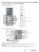
Page 26: ...at mode clock sleep mode set fan speed send signal X fan mode ventilation operation set temperature turbo mode set time TIMER ON TIMER OFF child lock light swing Temp display type set temp outdoor ambient temp indoor ambient temp health function I feel 2 3 6 8 11 13 14 1 7 4 5 9 10 12 15 red indicator the colour is different for different models ...

Page 27: ...on Service Manual AUTO COOL DRY FAN HEAT red indicator the red indicator the colour is red indicator colour is different for different models the colour is different for different models different for different models Press ...

Page 28: ...26 Technical Information Service Manual horizontal louvers stops at current position no display no display ...

Page 29: ...he MODE button and X FAN buttons simultaneously for 5s to cancel H1 display If remote controller displays H1 it belongs to the normal function reminder If the unit is defrosting under heating mode it operates according to H1 defrosting mode H1 won t be displayed on the panel of indoor unit Once you set H1 mode if you turn off unit by remote controller H1 will display 3 times on the remote controll...

Page 30: ...mperature is higher than 25 the unit will run as the COOL mode b For the cooling and heating unit if the ambient temperature is or lower than22 the unit will run as the HEAT mode c When the indoor ambient temperature is higher than 22 but lower than 26 the system will run at the FAN mode and the set temperature is 24 In this case if other indoor unit runs at the HEAT mode a mode conflict alarm wil...

Page 31: ...mperature sensor is adopted However if this temperature sensor fails the sensor located at the return air inlet will take the place For the cassette type floor ceiling type indoor unit Under all modes the return air temperature sensor is adopted b When the duct type cassette type or the floor ceiling type indoor unit works with the wired controller the ambient temperature sensor can be set in the ...

Page 32: ...blow off the moist inside the exchanger of the indoor unit to prevent mould growing after the unit is shut off a On condition that this function is activated when the On Off press button is operated the fan of the indoor unit will still run for ten minutes with the symbol BLOW displayed At this time the fan will stop as this function is deactivated b This function is unavailable under the AUTO FAN...

Page 33: ...unit adequately grounded The grounding wire can t be used for other purposes 6 Must apply protective accessories such as protective boards cable cross loop and wire clip 7 The live wire neutral wire and grounding wire of power supply must be corresponding to the live wire neutral wire and grounding wire of the air conditioner 8 The power cord and power connection wires can t be pressed by hard obj...

Page 34: ... liquid valve and gas valve are fully closed and power is disconnected before detaching the connection pipe If compressor starts running when stop valve is open and connection pipe is not yet connected air will be sucked in and cause pressure rise or compressor rupture resulting in injury When installing the unit make sure that connection pipe is securely connected before the compressor starts run...

Page 35: ...ing tape 4 Electroprobe 7 Electronic leakage detector 10 Pipe pliers pipe cutter 2 Screw driver 5 Universal meter 8 Vacuum pump 11 Pipe expander pipe bender 3 Impact drill drill head electric drill 6 Torque wrench open end wrench inner hexagon spanner 9 Pressure meter 12 Soldering appliance refrigerant container ...

Page 36: ...the installation does not comply with the requirements ƹ for Electrical Equipment relevant local rules and the installation instructions Make sure to use the special purpose circuit If the power circuit capacity is low or the construction is improper it might cause electric shock ƹ Please use suitable cables and connect them securely Please fix the terminal joints securely The terminal connection ...

Page 37: ...place where inflammable gas might leak Gas leakage and despot around the ƹ To ensure correct drainage of water the drainage pipe shall be installed according to the installation instructions Also the heat insulation shall be provided to avoid condensing Improper installation of the pipe might result in water leakage and lead to possible wetting of the articles in the room 7 1 2 Key Points of Insta...

Page 38: ...ing the tubes Please keep to the welding process and ensure the system free of leakage For multiple systems please mark them properly Carry out leakage detection under pressure after welding Purge and make leakage detection under pressure Purge the system clean Keep the pressure for 24 hours within 0 02MPa With the temperature change by 1 ć the pressure will change by approx 0 01MPa Thermal insula...

Page 39: ... indoor unit and outdoor unit Test run of indoor unit Air flow and noise level inspection Connection of power cables Purge and make leakage detection under pressure Connection of indoor unit and outdoor unit Leakage detection under pressure Add refrigerant Open the valve Commissioning of complete unit As built Drawing Delivery of the Operating Instructions meanwhile vacuum the system through the g...

Page 40: ...umidity Note The air conditioner unit installed in the following place may have malfunction if the malfunction cannot prevent please contact the Nominated Repair Center Of Gree Electric Appliances Inc Of Zhuhai a The place with greasy all around b The seashore place with salinity and alkali c The place with vulcanized gas such as vulcanized hot spring d The place with high frequency equipment such...

Page 41: ...39 Installation and Maintenance Service Manual ...

Page 42: ...40 Installation and Maintenance Service Manual 12 18K ...

Page 43: ...41 Installation and Maintenance Service Manual ...

Page 44: ...42 Installation and Maintenance Service Manual ...

Page 45: ...43 Installation and Maintenance Service Manual ...

Page 46: ...44 Installation and Maintenance Service Manual ...

Page 47: ...45 Installation and Maintenance Service Manual ...

Page 48: ...46 Installation and Maintenance Service Manual ...

Page 49: ...47 Installation and Maintenance Service Manual ...

Page 50: ...48 Installation and Maintenance Service Manual 9 Maintenance 9 1 Trouble Table ...

Page 51: ...49 Installation and Maintenance Service Manual ...

Page 52: ...50 Installation and Maintenance Service Manual ...

Page 53: ...51 Installation and Maintenance Service Manual ...

Page 54: ...52 Installation and Maintenance Service Manual ...

Page 55: ...53 Installation and Maintenance Service Manual ...

Page 56: ...d for details Malfunction of compressor Compressor can t operate Refer to point 5 of maintenance method for details 9 3 Maintenance Method for Normal Malfunction 1 Air Conditioner Can t be Started up 2 Poor Cooling Heating for Air Conditioner 3 Horizontal Louver Can t Swing Possible Causes Discriminating Method Air conditioner Status Troubleshooting No power supply or poor connection for power plu...

Page 57: ... pipe Replace drain pipe Wrapping is not tight Water leaking from the pipe connection place of indoor unit wrap it again and bundle it tightly 5 Compressor Can t Operate Possible causes Discriminating method air conditioner status Troubleshooting Wrong wire connection or poor connection Check the wiring status according to circuit diagram Connect wires according to wiring diagram to make sure all ...

Page 58: ...Service Manual 10 Exploded View and Parts List The component picture is only for reference please refer to the actual product TM09HEDI TM12HEDI 32 33 31 30 1 2 3 4 7 8 14 13 12 18 20 10 9 22 23 24 26 19 5 27 29 28 6 11 17 21 15 16 25 ...

Page 59: ...422000000022 1 13 Switch Board 30112007 30112007 1 14 Display Board 30568131 30568131 1 15 Fuse 46010055 46010055 1 16 Radiator 49010252 49010252 1 17 Signal Wire 4003004202 4003004202 1 18 Jumper 4202300101 4202300102 1 19 Main Board 30138613 30138613 1 20 Electric Box 20112116 20112116 1 21 Electric Box Assy 2020262201 2020262101 1 22 Air Louver upper 10512143 10512143 2 23 Swing Lever 10582096 ...

Page 60: ...tion and Maintenance Service Manual TM18HEDI 32 30 33 31 1 2 3 4 7 8 14 13 12 18 20 10 9 22 23 24 26 19 5 27 29 28 6 11 17 21 15 16 25 The component picture is only for reference please refer to the actual product ...

Page 61: ... 10102042 1 12 Terminal Board 422000000022 1 13 Switch Board 30112007 1 14 Display Board 30568131 1 15 Fuse 46010055 1 16 Radiator 49010252 1 17 Signal Wire 4003004202 1 18 Jumper 4202300103 1 19 Main Board 30138613 1 20 Electric Box 20112116 1 21 Electric Box Assy 2020242301 1 22 Air Louver upper 10512143 2 23 Swing Lever 10582096 2 24 Shaft of Guide Louver 10542020 2 25 Rear Grill 01472024 1 26 ...

Page 62: ...60 Installation and Maintenance Service Manual The component picture is only for reference please refer to the actual product TM12HKDI TM18HKDI ...

Page 63: ...ient Temperature Sensor 3900019813 3900019813 1 14 Filter Sub Assy 11120011 11120011 1 15 Clamp power cord 71010105 71010105 1 16 Filter Sub Assy 11120012 11128633 1 17 Water Tray Assy 20182704 20182704 1 18 Evaporator Support 01072714 01072714 1 19 Evaporator Assy 01024307 0102430701 1 20 Evaporator Connection Board 01072713 01072713 1 21 Centrifugal Fan 10312702 10312702 1 22 Fan Motor 157041140...

Page 64: ...62 Installation and Maintenance Service Manual TM24HKDI The component picture is only for reference please refer to the actual product ...

Page 65: ...troller 305125063 1 13 Connected Board Assy Of Evaporator 01074042 1 14 Filter Sub Assy 07210028 1 15 Drain Hose Sub Assy 05232702 1 16 Water Tray Assy 20182701 1 17 Electric Base Plate 1412721 1 18 Diversion Circle 10372701 1 19 Electric Box Assy 01399520 1 20 Transformer 43110233 1 21 Terminal Board 420001000002 1 22 Electric Box Cover I 20102702 1 23 Electric Box Cover Sub Assy1 20122054 1 25 A...

Page 66: ...64 Installation and Maintenance Service Manual The component picture is only for reference please refer to the actual product TM09HFDI TM12HFDI ...

Page 67: ...sformer 43110233 43110233 1 13 Terminal Board 420001000002 420001000002 1 14 Main Board 30226339 30226338 1 15 Capacitor 3301074701 3301074704 1 16 Electric Box Sub Assy 01395100 01395100 1 17 Electric Box assy 01395980 01395983 1 18 Electric Box Cover 01424253 01424253 1 19 Cover Plate of the Fan 01265300 01265300 1 20 Bottom Cover Plate 01265299 01265299 1 21 Supporter 01895225 01895225 1 22 Bar...

Page 68: ...66 Installation and Maintenance Service Manual The component picture is only for reference please refer to the actual product TM18HFDI ...

Page 69: ... 80050053 1 12 Transformer 43110233 1 13 Terminal Board 420001000002 1 14 Main Board 30226338 1 15 Capacitor 3301074704 1 16 Electric Box Sub Assy 1395100 1 17 Electric Box assy 1395984 1 18 Electric Box Cover 1424253 1 19 Temperature Sensor 39000206 1 20 Ambient Temperature Sensor 39000206 1 21 Cover Plate of the Fan 1265333 1 22 Fan Motor 150101000070 1 23 Bar Clasp 70818405 1 24 Supporter 18052...

Page 70: ...68 Installation and Maintenance Service Manual TM24HFDI The component picture is only for reference please refer to the actual product ...

Page 71: ...1265337 1 12 Transformer 43110233 1 13 Terminal Board 420001000002 1 14 Main Board 30226338 1 15 Capacitor 3301074704 1 16 Electric Box Sub Assy 01395100 1 17 Electric Box assy 01395985 1 18 Electric Box Cover 01424253 1 19 Cover Plate of the Fan 01265338 1 20 Temperature Sensor 39000206 1 21 Ambient Temperature Sensor 390001982G 1 22 Fan Motor 15010100007401 1 23 Bar Clasp 70818405 1 24 Supporter...

Page 72: ...70 Installation and Maintenance Service Manual The component picture is only for reference please refer to the actual product TM09HTDI TM12HTDI TM18HTDI TM24HTDI ...

Page 73: ...405 1 22 Bar Clasp Sub assy 70815201 70815201 70815201 1 23 Rear volute casing 26905206 26905206 26905206 4 24 Rubber ring 76513101 76513101 76513101 1 25 Filter 2 07216221 07216221 07216221 1 26 Ambient Temperature Sensor 390001978G 390001978G 390001978G 1 27 Evaporator Assy 01029482 01029469 1029474 1 28 Press Plate of Water Lead flume 26909442 26909442 26909442 1 29 Connection Board Evaporator ...

Page 74: ...72 Installation and Maintenance Service Manual 11 Removal Procedure 11 1 Removal Procedure of Indoor Unit Caution discharge the refrigerant completely before removal ...

Page 75: ...73 Installation and Maintenance Service Manual ...

Page 76: ...74 Installation and Maintenance Service Manual ...

Page 77: ...75 Installation and Maintenance Service Manual ...

Page 78: ...76 Installation and Maintenance Service Manual ...

Page 79: ...77 Installation and Maintenance Service Manual Floor ceiling type ...

Page 80: ...78 Installation and Maintenance Service Manual ...

Page 81: ...79 Installation and Maintenance Service Manual ...

Page 82: ...H EDFN VFUROO FDVH LIW WKH EXFNOH RI EDFN VFUROO FDVH ZLWK KDQGV DQG UHPRYH LW V LV VKRZQ LQ WKH JUDSK FLUFOH UHSUHVHQWV VFUHZV RQ OHIW DQG ULJKW 5HPRYH IDQV Ɣ5HPRYH WKH LQJ VFUHZV RI IDQ ZKHHO ZLWK LQQHU KH DJRQDO DQG UHPRYH WKH ZKHHO 7KH LQQHU KH DJRQDO DQG LWV GLUHFWLRQ RI HIIHFW DUH VKRZQ E WKH DUURZ LQ WKH JUDSK 5HPRYH EHDULQJ LQJ SODWHV Ɣ5HPRYH VFUHZV RQ WKH EHDULQJ LQJ SODWHV ZLWK VFUHZGULY...

Page 83: ... 6 12 77 78 77 25 Fahrenheit display temperature Fahrenheit Celsius Fahrenheit display temperature Fahrenheit Celsius Fahrenheit display temperature Fahrenheit Celsius 61 60 8 16 69 70 69 8 21 78 79 78 8 26 62 63 62 6 17 71 72 71 6 22 80 81 80 6 27 64 65 64 4 18 73 74 73 4 23 82 83 82 4 28 66 67 66 2 19 75 76 75 2 24 84 85 84 2 29 68 68 20 77 77 25 86 86 30 Union pipe Pipe Downwards Pipe Shaper Pi...

Page 84: ...according to the steps above The length is equal Improper expanding leaning damaged surface crack uneven thickness Smooth surface Expander Hard mold Pipe A is different according to the diameter please refer to the sheet below Outer diameter mm A mm Max Min Ф6 6 35 1 4 1 3 0 7 Ф9 52 3 8 1 6 1 0 Ф12 12 70 1 2 1 8 1 0 Ф16 15 88 5 8 2 4 2 2 Note ...

Page 85: ...8 6 66 88 33 10 63 72 2 439 111 0 737 5 63 46 34 10 2 73 2 358 112 0 717 4 60 23 35 9 779 74 2 28 113 0 697 3 57 18 36 9 382 75 2 206 114 0 678 2 54 31 37 9 003 76 2 133 115 0 66 1 51 59 38 8 642 77 2 064 116 0 642 0 49 02 39 8 297 78 1 997 117 0 625 1 46 6 40 7 967 79 1 933 118 0 608 2 44 31 41 7 653 80 1 871 119 0 592 3 42 14 42 7 352 81 1 811 120 0 577 4 40 09 43 7 065 82 1 754 121 0 561 5 38 1...

Page 86: ... 0 983 5 84 61 34 13 59 73 3 144 112 0 956 4 80 31 35 13 04 74 3 04 113 0 93 3 76 24 36 12 51 75 2 94 114 0 904 2 72 41 37 12 76 2 844 115 0 88 1 68 79 38 11 52 77 2 752 116 0 856 0 65 37 39 11 06 78 2 663 117 0 833 1 62 13 40 10 62 79 2 577 118 0 811 2 59 08 41 10 2 80 2 495 119 0 77 3 56 19 42 9 803 81 2 415 120 0 769 4 53 46 43 9 42 82 2 339 121 0 746 5 50 87 44 9 054 83 2 265 122 0 729 6 48 42...

Page 87: ...74 62 11 32 101 3 22 15 362 9 24 51 41 63 10 93 102 3 13 14 342 8 25 49 19 64 10 54 103 3 04 13 323 9 26 47 08 65 10 18 104 2 96 12 306 2 27 45 07 66 9 83 105 2 87 11 289 6 28 43 16 67 9 49 106 2 79 10 274 29 41 34 68 9 17 107 2 72 9 259 3 30 39 61 69 8 85 108 2 64 8 245 6 31 37 96 70 8 56 109 2 57 7 232 6 32 36 38 71 8 27 110 2 50 6 220 5 33 34 88 72 7 99 111 2 43 5 209 34 33 45 73 7 73 112 2 37 ...

Page 88: ...JF00304027 ...

Reviews: