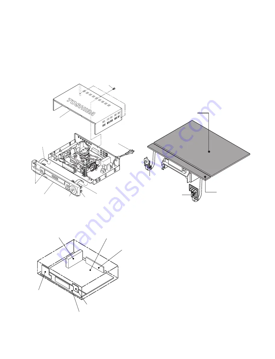
2. REMOVAL OF THE CABINET
(1) Unplug the power supply plug (1) from the outlet.
(2) Remove the three screws (3) securing the Top cover
(2).
(3) Pull the Top cover (2) backwards for removing.
(4) Disconnect the two FFC (4) flexible flat cables.
(5) Release the four claws (A) of the front panel (5) and
detach the front panel (5).
Fig. 2-1
3. LOCATION OF ELECTRICAL
UNITS
Fig. 3-1
FFC (4)
FFC (4)
Power Supply
Plug (1)
Screws (3)
Top cover (2)
Front panel (5)
Claw(A)
Claw (A)
Claw (A)
UK02 FCB PC Board
UK03 JSB PC Board
UK04 KDB PC Board
3 IN 1 Tuner
UZ01 Main PC Board
H301 VIDEO MODULE
UZ01 Main PC Board
UK04 KDB PC Board
UK02 FCB PC Board
UK03 JSB PC Board
Fig. 4-1
4. PC BOARD SERVICING PRO-
CEDURE
When performing service, connect each connection part
of the mechanical deck with the main PC board (two
connectors, two flexible flat cables), and then turn the
unit upside down with the mechanical deck integrated
with the main PC board.
Note:
• When unloading a tape due to power off and ejec-
tion, place the unit back to the normal position (from
the reversed position) to protect the tape before
performing unloading.


