background image

29

RECORDING

RECORDING

The flow chart below will give you an idea
as to what must be done to use the VCR
Plus+ C

3 ®

 system feature.

Setting the Clock (page 16)

Cable Box Set-up (page 33)

Storing Channels on the VCR

(page 17)

VCR Plus+ C

3 ®

 system Set-up

VCR Plus+ C

3 ®

 system Recording

(page 31)

* With the VCR Plus+ C

3 ®

 system, this video

cassette recorder can automatically select the
appropriate channel on your compatible cable
box or satellite receiver. VCR Plus+, C

3

 and

PlusCode are registered trademarks of
Gemstar Development Corporation. The VCR
Plus+ system is manufactured under license
from Gemstar Development Corporation.

You must give the VCR the special
numbers for guide channels (also called
VCR Plus+

®

 system channel numbers)

assigned to each channel that you receive
in your home.  The VCR identifies the
channel to be recorded by the guide
channel number you enter.
The guide channel numbers are published
in TV guide magazine, selected local TV
publications, or the channel guide from
cable company.  If you cannot find the
numbers, call Gemstar’s customer service
department at 1-800-4321-VCR.

Sample of a Guide channel chart from a local TV listing

Sample of a Channel line-up chart from a cable-TV
company

CHANNEL LINE-UP CHART

Channel 2

Channel 3

Channel 4

Channel 5

Channel 6

Channel 7

Channel 8

Channel 9

ME/U

8 WISH

4 WTTV

6 WRTV

VCA/Local origination

HOME BOX OFFICE

A.P News Plus

9 WGN.

3   KCRA (NBC).................3

VCR Plus+

®

 SYSTEM CHANNEL NUMBERS

6   KVIE (PBS)...................6

10  KXTV (CBS)................10
13  KOVR (ABC)...............13
19  KCSO (SPAN).............19
31  KRBK (IND).................31

Broadcast
channels

Assigned

channels

A & E........................39
AMC......................... 35
BET..........................57
BRAV....................... 54
CMTV.......................14
CNBC.......................23

Assigned

channels

Cable
channels

40  KTXL (FOX)................ 40
58  KSCH (IND)................ 25
44  KBHK (IND).................15
24  KCPM (NBC)...............24

4  KRNV (NBC)...............28

42  KFCB (IND).................27

7  KGO (ABC)................. 28

CNN......................... 42
C-SPAN....................28
CUNY....................... 29
DIS...........................53
ESPN....................... 34
FAM......................... 47
HBO......................... 33

VCR Plus+ C

3 ®

 system

 Set-up

VCR Plus+ C

3 ®

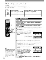
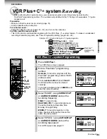
 system is a timer recording system for an easier programming that requires you only to

enter a PlusCode

®

 programming number assigned to a desired program.  This section explains the

necessary set-up to make VCR Plus+ C

3 ®

 system recordings.

Summary of Contents for W-707

Page 1: ...Video Cassette Recorder W 707 OWNER S MANUAL This publication is printed on recycled paper 70971855 PLAY STOP PROG TV POWER EJECT PAUSE STILL REC REV FF ...

Page 2: ... or modification made to this equipment not expressly approved by Toshiba Corporation or parties authorized by Toshiba Corporation could void the user s authority to operate the equipment Note to CATV system installer This reminder is provided to call the CATV system installer s attention to Article 820 40 of the NEC that provides guidelines for proper grounding and in particular specifies that th...

Page 3: ...nder inside one of its most crucial internal parts To prevent the VCR from possible damage do not use the unit for at least 2 hours when there is an extreme or sudden change in temperature Compatibility This video cassette recorder VCR is compatible with any other VCR bearing the mark HQ VHS equipment is also compatible with existing non HQ VHS equipment Copyright It is permissible to record telev...

Page 4: ... operation of the product and to protect it from overheating and these openings must not be blocked or covered The openings should never be blocked by placing the product on a bed sofa rug or other similar surface This product should not be placed in a built in installation such as a bookcase or rack unless proper ventilation is provided or the manufacturer s instructions have been adhered to 5 He...

Page 5: ... SERVICE EQUIPMENT GROUNDING CONDUCTORS NEC SECTION 810 21 GROUND CLAMPS POWER SERVICE GROUNDING ELECTRODE SYSTEM NEC ART 250 PART H NEC NATIONAL ELECTRICAL CODE S2898A 10 Outdoor Antenna Grounding If an outside antenna or cable system is connected to the product be sure the antenna or cable system is grounded so as to provide some protection against voltage surges and built up static charges Arti...

Page 6: ...e or electric shock Never spill liquid of any kind on the product 15 Accessories Do not place this product on an unstable cart stand tripod bracket or table The product may fall causing serious injury to a child or adult and serious damage to the product Use only with a cart stand tripod bracket or table recommended by the manufacturer or sold with the product Any mounting of the product should fo...

Page 7: ...ACK Explains variable functions concerning playback Playback 20 19µ HEAD Variable Speed Playback 21 Picture Search Still Picture Slow motion Picture Frame Advance Double Speed Playback Jog Dial Operation Shuttle Dial Operation Useful Functions in Tape Operation 23 Counter Function Tape Remaining Time Index Search Function RECORDING Explains recording functions Recording a TV Program 25 Watching a ...

Page 8: ...T c TV POWER SELECT INPUT SELECT VCR TV 1 2 3 DISPLAY COUNTER REMAIN RESET COUNT 4 5 6 TV VCR SP SLP TV VOL A SELECT 7 8 9 0 a CH TRK 8 9 SLOW J PAUSE STILL 100 REC TIMER PLAY STOP F F REW REC VCR Plus POWER CABLE BOX 19µ ENTER CANCEL PROG CH INDEX REV FWD L TV POWER CH TRK CANCEL TV VCR CURSOR RIGHT TIMER TV Number buttons JOG dial SHUTTLE dial SP SLP 20 21 15 19 REW SLOW VCR POWER PAUSE STILL EN...

Page 9: ... SP SLP Cassette indicator Timer recording indicator REMAIN indicator OFF indicator Hi Fi L R indicators L Left channel R Right channel off Normal track VCR Display POWER indicator DT Digital Auto Tracking indicator Channel indicator Tape running direction speed indicator REMAIN VCR SLP L REC TIMER DT CH H M AM PM OFF S R POWER LINE IN 1 VIDEO jack LINE IN 1 AUDIO jacks L R To wall outlet CH selec...

Page 10: ...onditions of use If the remote control does not operate correctly replace all batteries with new ones If the remote control is not to be used for a long period of time remove the batteries to avoid possible damage from battery corrosion Caring for the remote control Do not expose the remote sensor of the VCR to a strong light source such as direct sunlight or illumination especially high frequency...

Page 11: ...Setting the VCR Output Channel When the VCR is connected in this way the VCR sends the output signals to channel 3 or 4 on your TV Set the output channel selector CH selector of the VCR to 3 or 4 whichever is vacant in your area VHF UHF combinaion antenna VHF antenna only UHF antenna only Antenna splitter not supplied 1 2 Connections Before you use this VCR it is necessary to connect it to your TV...

Page 12: ...isplay and select a desired channel on the TV only when you connect a cable compatible TV This set up will enable you to record an unscrambled channel watch an unscrambled channel while recording it record an unscrambled channel while watching another scrambled or unscrambled You will need to set TV channel to the output channel of the cable box turn on the cable box and select cable channel 3 or ...

Page 13: ...f the cable box This set up will enable you to watch an unscrambled or scrambled channel while recording it record an unscrambled channel while watching another unscrambled channel only when you connect a cable compatible TV A B switch A record and watch an unscrambled channel which comes bypassing the cable box A B switch B record and watch a scrambled or unscrambled channel coming through the ca...

Page 14: ... and clock when power is first connected to the VCR Preparation Turn on the TV and select the video channel 3 or 4 or the video input mode if you made the Audio Video connection page 11 Press INPUT SELECT so that the channel number will appear if L1 or L2 is displayed in the VCR display Press VCR to set the remote control operating the VCR Tuning in progress Auto Set Up completed VCR display Notes...

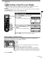
Page 15: ...the TV 3 Select the language using CURSOR UP or CURSOR DOWN and press PROG The screen turns to the MENU screen 4 Press PROG to return to the normal TV screen Page 23 PREPARATION Initial Settings Using On screen Display Language selection must be set first when the VCR is first plugged in or after it encounters a power failure You can also easily make necessary settings using the on screen displays...

Page 16: ...HT or CURSOR LEFT Change the data using CURSOR UP or CURSOR DOWN 1 Set SUMMER TIME Daylight Saving Time IN daylight saving time begins on the first Sunday in April Because the clock automatically changes from 2 00 AM to 3 00 AM forward one hour remember that any part of a scheduled Timer Recording that falls between these two times will not be recorded OUT daylight saving time ends on the last Sun...

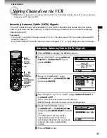
Page 17: ...R RIGHT or CURSOR LEFT TV To store channels received via the antenna CATV To store channels received via the incoming cable 5 Select AUTO SCAN using CURSOR UP or CURSOR DOWN and press CURSOR RIGHT to set to On The VCR starts scanning and the channels are stored in the VCR in ascending order When the scanning is finished the screen automatically returns 6 Press PROG to exit PREPARATION Storing Chan...

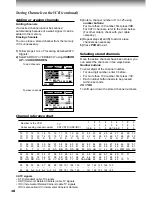
Page 18: ...6 47 48 49 50 51 31 32 33 34 35 36 37 38 39 40 41 42 43 44 45 46 47 48 49 50 51 R S T U V W AA BB CC DD EE FF GG HH II JJ KK LL MM NN OO 52 53 54 55 56 57 58 59 60 61 62 63 64 65 66 67 68 69 70 71 52 53 54 55 56 57 58 59 60 61 62 63 64 65 66 67 68 69 PP QQ RR SS TT UU VV WW XX YY ZZ AAA BBB 65 66 67 68 69 70 71 93 94 95 96 97 98 99 100 101 102 103 121 122 123 124 125 93 94 A 5 A 4 A 3 A 2 A 1 100 ...

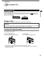
Page 19: ...tment This may result in injury or damage Take special care with children to avoid accidents Precautions when using video cassettes Video cassettes have a safety tab to prevent accidental erasure If the tab has already been removed recording cannot be performed To prevent accidental erasure Remove this safety tab with a screwdriver To record again Cover the tab hole with adhesive tape Avoid exposi...

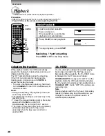
Page 20: ...ictures while playing back a tape recorded in the SLP tape speed By pressing 19µ repeatedly the 19µ HEAD mode is displayed on the TV screen as follows 19U HEAD AUTO Usually set to AUTO As the playback starts the VCR automatically activates the 19µ head and reproduces high quality pictures 19U HEAD OFF Set to OFF if the pictures are marred by dots Note During playback with the 19µ head momentary no...

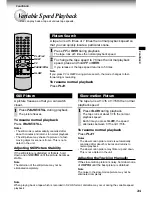
Page 21: ...is frozen This is not a defect in the unit Adjusting Still Picture Stability If the still picture is distorted or flickers hold down one of CH TRK until the picture becomes stable Note The distortion of the still picture may not be eliminated completely Slow motion Picture The tape runs at 1 7th or 1 15th the normal playback speed 1 Press SLOW during playback The tape runs at about 1 7th the norma...

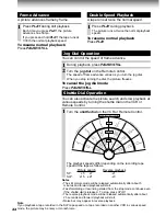
Page 22: ...k Jog Dial Operation You can control the speed of frame advance 1 During playback press PAUSE STILL 2 Turn the jog dial on the Remote Control The speed of frame advance varies as you turn the jog dial When you stop turning the dial the picture freezes To cancel the jog dial mode Press PAUSE STILL Shuttle Dial Operation You can also activate the picture search and slow playback at various speeds by...

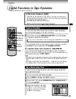
Page 23: ...ning Time To view the tape remaining time in the VCR display select the tape length beforehand 1 Turn on the VCR and load a cassette 2 Press PROG to display the MENU screen 3 Select SET UP using CURSOR RIGHT or CURSOR LEFT and press ENTER 4 Select the length of the tape T120 for a T 120 tape or shorter T160 for a T 140 or T 160 tape T180 for a T 180 tape Useful Functions in Tape Operation These fu...

Page 24: ...n index signal is found the VCR plays back the tape for about 5 seconds and then resumes fast forwarding or rewinding This is repeated each time at an index signal 3 Press PLAY when the desired program is found Normal playback starts Notes At the very beginning of the tape the index search may not work properly If you registered the index signals on a tape recorded on another VCR the recording may...

Page 25: ... but with less picture and sound quality than using the SP tape speed 5 Press REC on the VCR or simultaneously press both REC on the remote control Recording starts 6 Press STOP to stop recording Recording off time setting By setting the recording off time the recording stops and the VCR is turned off automatically While recording press REC on the VCR repeatedly to set the desired off time Each ti...

Page 26: ...ord a TV CATV program on the channel not a satellite s If your DSS satellite receiver is not remote controllable choose the desired channel 100 to 999 on the DSS satellite receiver To make corrections Press CURSOR LEFT to move back to the item or CURSOR RIGHT to forward Timer Program Recording The programmable timer allows you to record up to 6 different programs over one month Preparation Select ...

Page 27: ... tape is long enough for timer program recording in the SP tape speed set the recording tape speed to AUTO Recording starts in the SP tape speed and the VCR automatically selects the tape speed to record the program to the end If the tape length is not long enough the tape speed automatically changes from SP to SLP TIMER POWER PROG 25 8 30 9 30 10 00 E D n On CH DATE OFF D P S PM PMSP PROGRAM SET ...

Page 28: ...een disappears Changing cancelling the timer programs 1 If the TIMER indicator is lit press both TIMER to turn it off and then turn the VCR on by pressing VCR POWER 2 With steps 2 to 9 change the items To cancel a program select the program you want to cancel in step 4 and press CANCEL The line is then cleared 3 Press both TIMER to return to the timer standby mode Recording or playback in the time...

Page 29: ...ted local TV publications or the channel guide from cable company If you cannot find the numbers call Gemstar s customer service department at 1 800 4321 VCR Sample of a Guide channel chart from a local TV listing Sample of a Channel line up chart from a cable TV company CHANNEL LINE UP CHART Channel 2 Channel 3 Channel 4 Channel 5 Channel 6 Channel 7 Channel 8 Channel 9 ME U 8 WISH 4 WTTV 6 WRTV ...

Page 30: ...to exit The set up is all over and your VCR Plus C3 system recording is now available Example Station Your home channel number on the channel line up chart supplied by cable companies Guide channel number on the TV Guide local TV listings etc HBO 33 7 ESPN 34 AMC 35 the case of CATV mode Preparation Select the video channel 3 or 4 or video input mode on the TV If you record cable channels finish t...

Page 31: ...sure that the clock is set correctly page 16 Load a cassette with a safety tab For cable box users Finish the cable box set up pages 33 36 and turn on the cable box For DSS satellite receiver users This VCR cannot record satellite programs with the VCR Plus C3 system feature To make an unattended recording of satellite programs see Timer Program Recording pages 26 28 Sample of TV program listing i...

Page 32: ...by mode TIMER POWER Recording or playback in the timer standby mode First press both TIMER to release the timer standby mode and then press VCR POWER to turn on the VCR The VCR will be available for use Be sure to press both TIMER again to return the VCR to the timer standby mode after you have finished Error indications If FULL CANCEL PROG message appears on the TV during programming no more prog...

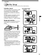
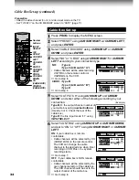
Page 33: ... block the sensor window The infrared signals come out of the sensor window and the front of the VCR Then they bounce off walls and other objects in the room and are received by the cable box The VCR sends out infrared signals to your cable box even during timer program recording or VCR Plus C3 system recording Notes If the channels cannot be controlled properly because the infrared signal fails t...

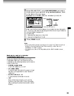
Page 34: ...able Cable channels will be selected by CH CABLE BOX on the remote control The VCR can change the cable channel to the desired one when timer recording or VCR Plus C3 system recording starts Go to step 7 OFF if your cable box is NON remote controllable Cable channels will be selected by the own channel selector of the cable box The VCR channel should be set to the output channel of the cable box G...

Page 35: ...hannels in the timer recording In this case set CONTROL to OFF in step 6 The cable box control is not compatible with the DSS satellite receiver control Buttons to control a remote controllable cable box Once you complete the set up for a remote controllable cable box your cable box can be controlled by the following buttons on the remote control of the VCR POWER CABLE BOX To turn the cable box on...

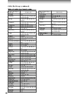
Page 36: ...0 11 12 13 46 OAK Sigma 10 11 12 13 46 Panasonic 6 8 16 17 Philips 4 13 20 21 22 23 24 25 26 58 62 84 Pioneer 5 6 78 Pulsar 30 42 44 52 63 88 Randtek 13 20 21 22 23 24 25 26 58 62 84 RCA 6 8 16 17 Realistic 44 88 Regal 14 23 41 84 Regency 26 28 Rembrandt 29 32 38 39 42 44 88 Samsung 4 6 32 42 78 Scientific Atlanta 8 9 56 61 Sheritech 27 SL Mark 4 6 32 42 78 Sprucher 6 8 16 17 Stargate 4 6 30 32 42...

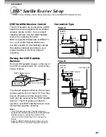
Page 37: ...hown below Do not block the sensor window The infrared signals come out of the sensor window and the front of the VCR Then they bounce off walls and other objects in the room and are received by the DSS satellite receiver The VCR sends out infrared signals to your DSS satellite receiver even during timer program recording Notes If the channels cannot be controlled properly because the infrared sig...

Page 38: ... receiver is remote controllable Satellite channels will be selected by CH CABLE BOX on the remote control The VCR can change the satellite channel to the desired one when timer recording starts Go to step 7 Preparation Select the video channel 3 or 4 or video input mode on the TV Example TV VCR 1 2 3 4 5 6 7 8 9 0 a 8 9 J PROG REV FWD L POWER CABLE BOX CH CABLE BOX ENTER PROG Number buttons SP SL...

Page 39: ...t channel of the DSS satellite receiver Go to step 8 7 Select BRAND TYPE using CURSOR DOWN and enter a brand code of your DSS satellite receiver using number buttons Refer to the table on the next page Example For a TOSHIBA DSS satellite receiver identified by number 99 Make sure that the background of the above display has changed to the satellite program on channel 200 If not relocate the DSS sa...

Page 40: ...nd track Contents of recorded sound On Screen Display Press DISPLAY Setting of SAP SET on the SET UP screen Type of receiving broadcast Normal sound track Mono L R SAP STEREO ON or OFF not lit not lit MONO MONO MONO ON or OFF not lit lit MONO MIXED ON lit not lit MONO MONO SAP OFF lit not lit MONO MONO MONO ON lit lit MONO MONO SAP OFF lit lit MONO MIXED STEREO STEREO Regular monaural audio Stereo...

Page 41: ...R DOWN and set to ON using CURSOR LEFT or CURSOR RIGHT 2 Press PROG to exit 3 Select the desired channel using CHANNEL on the VCR or CH TRK on the remote control If you use a cable box select a desired channel on the box 4 Select the recording tape speed using SP SLP 5 Press REC to start recording 6 Press STOP to stop recording Broadcast or incoming cable RECORDING To the FM antenna terminal TV VC...

Page 42: ...te for 100 channel key DISPLAY To turn on or off TV s screen display ENTER To use for the TV s ENTER key Important Some TVs may not respond to all the operations above or may not be operated at all with this remote control In this case operate your TV with its own remote control Notes For some brands several control codes brand codes are allocated Try each of them until the buttons work on your TV...

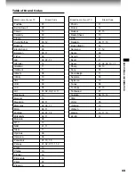
Page 43: ...ola 08 MTC 12 NAD 01 11 Nikko 11 Optimus 09 Optonica 08 Panasonic 07 10 15 Penney 01 02 07 11 12 Philco 10 Philips 10 Pioneer 16 Princeclub 12 Prism 07 Proscan 02 Table of Brand Codes Proton 11 Pulser 14 Quasar 07 15 Radio Shack 13 RCA 02 Realistic 09 11 13 Runco NEC 14 Samsung 11 12 Sanyo 09 Scotch 11 Scott 11 Sears 01 02 09 10 11 Sharp 08 13 Sony 03 Soundesign 11 Supreme 03 Sylvania 10 Tandy 08 ...

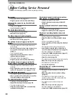
Page 44: ...cially available cleaning tape The desired sound is not heard such as SAP stereo or regular sound Setting of sounds is not correct Select a desired sound using A SELECT page 40 Noise is present in the Hi Fi sound being played Tracking is not set appropriately Adjust the tracking manually page 20 The timer recording function does not work There is an error in programming Reset the timer recording p...

Page 45: ...ront of the VCR page 10 An obstacle may be in the way of the operation Remove the obstacle The operating mode of the remote control is not set correctly Press VCR or TV depending on the equipment you want to operate pages 14 42 The cassette is ejected immediately after it is loaded The cassette was inserted with the label side not paralleling the compartment Reload it carefully page 19 The cassett...

Page 46: ...minutes When T 160 video cassette is used Fast forward time Within approx 80 s When T 120 video cassette is used High speed rewind time Within approx 54 s when T 120 video cassette is used Video input 1 V p p 75 Ω unbalanced negative sync pin jack Video output 1 V p p 75 Ω unbalanced negative sync pin jack Audio input Line input 308 mV rms more than 47 kΩ pin jack Audio output Line output 308 mV r...

Page 47: ...n you this product as a gift purchased this product This is one way to enable TACP THI to provide you with better customer service and improved products Failure to return the card will not affect your rights under this warranty Your Responsibility The above warranties are subject to the following conditions 1 You must retain your bill of sale or provide other proof of purchase 2 You must notify an...

Page 48: ... person agent distributor dealer or company is authorized to change modify or extend the terms of these warranties in any manner whatsoever The time within action must be commenced to enforce any obligation of TACP THI arising under the warranty or under any statute or law of the United States or any state thereof is hereby limited to ninety 90 days from the date you discover or should have discov...

Page 49: ...vicingTime 1 4 Mechanism Check Method 1 5 Mechanical Deck Removing and Mounting Method 1 6 Main Parts Replacement 1 7 Check and Adjustment 1 8 Self Check Function 2 ELECTRICAL ADJUSTMENT 2 1 PIF Circuit 2 2 Servo Circuit Top General Descriptions Servicing Diagrams Parts List Top General Descriptios Servicing Diagarms Part List ...

Reviews: