background image

4

5.

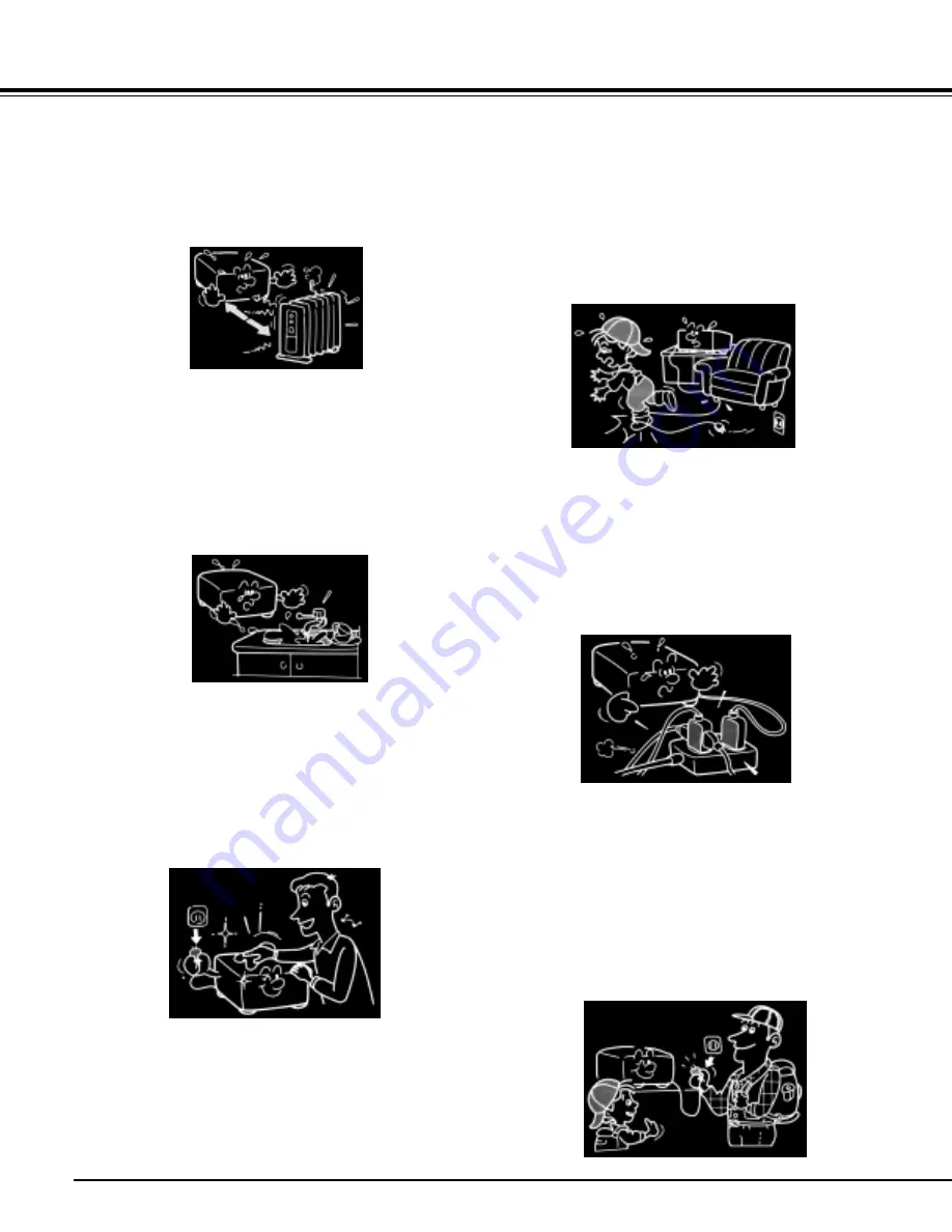
Heat

The product should be situated away
from heat sources such as radiators,
heat registers, stoves, or other products
(including amplifiers) that produce heat.

8.

Power-Cord Protection

Power-supply cords should be routed so
that they are not likely to be walked on
or pinched by items placed upon or
against them, paying particular attention
to cords at plugs, convenience recep-
tacles, and the point where they exit from
the product.

6.

Water and Moisture

Do not use this product near water.
- for example, near a bath tub, wash
bowl, kitchen sink, or laundry tub; in a
wet basement; or near a swimming pool
and the like.

9.

Overloading

Do not overload wall outlets; extension
cords, or integral convenience recep-
tacles as this can result in a risk of fire
or electric shock.

7.

Cleaning

Unplug this product from the wall outlet
before cleaning. Do not use liquid clean-
ers or aerosol cleaners.
Use a soft cloth for cleaning.

10. Lightning storms

For added protection for this product
during storm, or when it is left unat-
tended and unused for long periods of
time, unplug it from the wall outlet. This
will prevent damage to the product due
to lightning and power-line surges.

IMPORTANT SAFETY INSTRUCTIONS

Summary of Contents for TDP-MT500

Page 1: ...OWNER S MANUAL DATA PROJECTOR TDP MT500 ...

Page 2: ...uant to part 15 of the FCC Rules These limits are designed to provide reasonable protection against harmful interference in a residential installation This equipment generates uses and can radiate radio frequency energy and if not installed and used in accordance with the in structions may cause harmful interference to radio communications How ever there is no guarantee that interference will not ...

Page 3: ...ould be operated only from the type of power source indicated on the marking label If you are not sure of the type of power supply to your home consult your product dealer or local power company For products intended to operate from battery power or other sources refer to the operating instructions 3 Source of Light Do not look into the lens while the lamp is on The strong light from the lamp may ...

Page 4: ...example near a bath tub wash bowl kitchen sink or laundry tub in a wet basement or near a swimming pool and the like 9 Overloading Do not overload wall outlets extension cords or integral convenience recep tacles as this can result in a risk of fire or electric shock 7 Cleaning Unplug this product from the wall outlet before cleaning Do not use liquid clean ers or aerosol cleaners Use a soft cloth...

Page 5: ...ps heat and may give some un desirable damage to other unit 14 Attachments Do not use attachments not recom mended by the product manufacturer as they may cause hazards 15 Accessories Do not place this product on an unstable cart stand tripod bracket or table The product may fall causing serious injury to a child or adult and serious damage to the product Use only with a cart stand tripod bracket ...

Page 6: ... When the product exhibits a distinct change in performance this indicates a need for service 19 Replacement Parts When replacement parts are required be sure the service technician has used replacement parts specified by the manufacturer or have the same charac teristics as the original part Unautho rized substitutions may result in fire electric shock or other hazards Replacement of the lamp onl...

Page 7: ...he projector is finished to use Turn off POWER button to bring the pro jector into its standby state with the light source lamp off Then wait about 2 min utes and turn off the main power switch and be sure to unplug the power plug for safety Wait about 2 minutes in standby state because during this time the intake exhaust fan is operating to cool down the light source lamp Turn ing off the main po...

Page 8: ... cold location to a warm location When the unit is exposed to such a change in temperature moisture may condense on the crucial internal parts To prevent the unit from possible damage do not use the unit for at least 2 hours when there is an extreme or sudden change in temperature Place and Manner of Installation Do not place in hot locations such as near heating equipment Doing so could cause mal...

Page 9: ...No located at the bottom of your projector Model No Serial No Retain this information for future reference DECLARATION OF CONFORMITY TRADE NAME DLP DATA PROJECTOR MODEL NAME TDP MT500 RESPONSIBLE PARTY TOSHIBA AMERICA INFORMATION SYSTEMS INC 9740 Irvine Blvd Irvine CA 92618 1697 U S A Phone 949 583 3000 This device complies with part 15 of the FCC Rules Operation is subject to the following two co...

Page 10: ... A Connecting the projector to video equipment B Plugging power cord 20 C Making projection 21 D On setting ASPECT Image angle 23 E Connecting this projector with a computer 24 F Plugging power cord 24 VIWING COMPUTER IMAGES 24 A Connecting the projector with a computer 24 B Plugging power cord 24 C Making projection 25 SETTING WITH MENUS Menu construction 27 How to make menu setting 28 Items that...

Page 11: ...ry side If the battery is forced to insert in this way the outer label of the battery may get ripped and it may cause short circuit and heating 3 Attach the rear lid Use two size AAA dry batteries RO3 Exchange the two batteries to new ones if the distance that allows the remote controller to operate becomes shorter than usual Correctly treat the batteries after thoroughly reading On treating the b...

Page 12: ...r Pr ENTER WIDE TELE LAMP TEMP MENU EXIT POWER Main power switch I Turn on O Turn off Remote controller photo sensor Rear Theft prevention lock hole Power cable inlet Exhaust vent Angle adjusting button 11 36 17 10 VEDEO terminal Connects to such equipment as video players that output composite video signals Zoom ring Expands projected picture images when turned to the right WIDE Contracts project...

Page 13: ...ame and function of operational parts of remote controller On the picture quality adjusting buttons When any of the picture quality adjusting button is pressed its corresponding screen for adjusting the picture quality appears Then adjust the picture quality by pressing and button The picture quality adjustment can also be made in the picture quality menu See Page 26 The following picture quality ...

Page 14: ...he characteristics of the screen 15 15 15 15 15 15 Operational range of remote controller Keep the remote controller photo sensor away from the direct sun light or fluores cent lamp light Keep the remote controller photo sensor at least 2 m apart from fluorescent lamps Otherwise the remote controller may malfunction If there is an inverter operated fluores cent lamp near the remote controller the ...

Page 15: ...degrees 2 Press up the left and right angle adjusting buttons 3 Release the hands from the angle adjusting but tons and projector 5 Slowly lift down the projector by pressing the left and right angle adjusting buttons while holding the projector by hands It is also possible to adjust the projection angle by turn ing the angle adjusting foot rear to the lift or right If the projected image frame is...

Page 16: ... 187 332 544 650 68 64 180 224 399 653 780 82 77 Unit cm Screen size Height Screen size Height Projection distance L Projection distance L Screen Screen Projector Projector A 66mm Screen size Screen size A B Screen size and Projection distance Determine screen size by referring to the following table Where the screen size is 16 9 Where the projector is suspended from the ceiling In the case of usi...

Page 17: ...433 517 54 51 149 140 213 284 466 557 58 55 160 150 229 305 500 597 62 59 171 180 274 366 600 716 75 71 206 Projection height H Unit cm Projection height H Projection height H Screen size Projection distance L Screen Screen Projector Projector A A 66mm B Screen size Projection distance L Where the screen size is 4 3 Where the projector is suspended from the ceiling In the case of using suspension ...

Page 18: ... in this projector To reproduce audio signals connect audio equipment Consult the delivery agent of this projector on the detailed connections as needed Connecting to DVD players When connecting this projector to a video equipment that has component video output terminals such as DVD players connect video cables to COMPONENT 1 or 2 terminals Playback picture images of some of DVD players may not b...

Page 19: ...ENT 1 or 2 terminal Playback picture images of some of DVD players may not be able to be properly projected on screen Connecting to video equipment that has DVI D terminal The DVI terminal of this projector makes it possible to project high quality video images on screen by connecting with a video equipment that has DVI D terminal Also because this projector is in conformity with HDCP it is possib...

Page 20: ...o the other end of the power cable 3 Connect the U shaped metal of the conversion adaptor to the earthing terminal of the power outlet Earthing connection If there is no earthing terminal with the power outlet ask the delivery agent of this projector for the earthing work To be charged Be sure to make earthing connection before connecting the power plug to the power outlet Further when dis connect...

Page 21: ...rces contained in the signal setting menu See Page 26 for the details Some projected picture images may be made easy to see by chang ing ASPECT image angle See Page 20 for the details 4 Set the projector after adjusting the projec tion distance to obtain specified image frame size 5 Set the projector and screen so that they may face perpendicular to each other See Page 11 If the projector and the ...

Page 22: ...e cooling down but it is not a failure 11 Turn OFF the main power switch Turn to indication O When the projector is not used for a long time unplug the power plug from the power outlet for safety Set the lens cap to prevent dust from being gathered from outside VIEWING VIDEO IMAGES ENTER WIDE TELE LAMP TEMP MENU EXIT POWER Main power switch POWER button POWER button POWER indicator POWER ON OFF C1...

Page 23: ...OOM button In cinemascope mode it is possible to shift the display position with buttons 16 9 4 3 ZOOM REAL DYNAMIC Picture images with a ratio of 4 3 480i 576i 480p 576p and PC Cinemascope and vista signals with a ratio of 4 3 Projected images expand in horizontal direction PC inputs not less than SVGA are projected on full screen 16 9 Squeezed 4 to 3 images 480i 576i 480p 576p 16 to 9 images 108...

Page 24: ...N This projector does not comply with chrominance signals In the case of digital connections 1 Connect a commercially available DVI cable to DVI terminal of this projector 2 Connect the other end of the DVI cable to DVI terminal of the computer A conversion connector analog RGB output adaptor and or the like may be needed depending on the type of computer to be connected If a long cable other than...

Page 25: ...menu See Page 26 for the details Picture images of some input signals may not be projected on the proper position of the screen On this occasion execute AUTO in the signal setting menu of the setting menu See Page 30 4 Set the projector after adjusting the projec tion distance to obtain specified image frame size 5 Set the projector and screen so that they may face perpendicular to each other See ...

Page 26: ...le cooling down but it is not a failure 11 Turn OFF the main power switch Turn to indication O When the projector is not used for a long time unplug the power plug from the power outlet for safety Set the lens cap to prevent dust from being gathered from outside VIEWING COMPUTER IMAGES ENTER WIDE TELE LAMP TEMP MENU EXIT POWER Main power switch POWER button POWER button POWER indicator POWER ON OF...

Page 27: ...R2 CINEMA1 CINEMA2 VIDEO1 VIDEO2 STANDARD VIDEO S VIDEO COMPONENT1 COMPONENT2 DVI DIGITAL DVI ANALOG 16 9 4 3 ZOOM DYNAMIC REAL MEMORY1 MEMORY2 MEMORY3 YES NO 0 10 20 30 40 50 60 70 80 90 MINUTES 9300 6500 5700 USER1 USER2 LOAD FROM 10 10 ICC RED ICC GREEN SHARPNESS ICC BLUE R GAIN G GAIN B GAIN R BIAS G BIAS B BIAS SAVE TO GAMMA 1 512 1 512 1 512 0 90 0 90 0 90 USER1 USER2 SET USER COLOR TEMP MIR...

Page 28: ...owing figures describe how to set trapezoidal correction as an example 1 Press MENU button Main menu the first level appears 2 Select the menu to be revealed by pressing buttons 3 Press ENTER button The desired menu the second level appears 4 Select the menu to be revealed by pressing buttons 5 Press ENTER button The desired menu the third level appears 6 Press buttons for the setting When canceli...

Page 29: ... from a video equipment connected to COMPONENT2 terminal DVI DIGITAL Select when viewing picture images from a digital equipment connected to DVI terminal DVI ANALOG Select when viewing picture images from an analog equipment connected to DVI terminal ASPECT 16 9 Sets picture images to be projected to an aspect ratio of 16 9 4 3 Sets picture images to be projected to an aspect ratio of 4 3 ZOOM Pr...

Page 30: ...stment The items with mark function only for 1080i 720p 525p and 625p input signals and input signals from DVI terminal The varying range of the vertical position depends on the type of the input signal With some values the vertical position may not change but this is not a failure With the inputs from DVI DIGITAL terminal no change appear on the projected images with adjustment of the dividing ra...

Page 31: ...f projected picture images Every time button is pressed the colors are made thicker Every time button is pressed the colors are made thinner TINT Adjusts tint of projected picture images Every time button is pressed the skin color of the projected images is made more reddish Every time button is pressed the skin color is made more greenish Setting projected images sharper or softer SHARPNESS Sharp...

Page 32: ...User 1 or User 2 by pressing buttons buttons 10 Press ENTER button Åú The set color temperatures are stored in the memory To cancel the menus 11 Press MENU button To bring one of the set color temperatures Select User 1 or User 2 in Setting color temperatures of the professional use picture quality setting menu On color temperatures There is various degree of white color One of the methods of repr...

Page 33: ...al position in the signal setting menu Every time button is pressed the projected image is shifted to the left Every time button is pressed the projected image is shifted to the right Projected images are shifted up or down Åc Adjust Vertical position in the signal setting menu Every time button is pressed the projected image is shifted downward Every time button is pressed the projected image is ...

Page 34: ...than 1500 hours of use the power for the lamp is automatically turned off and the lamp can not be used any more Then replace the lamp to new one as soon as possible Do not remove the light source lamp except when it is replaced Otherwise removing it may cause a failure As the light source lamp the high pressure mercury lamp is used The high pressure mercury lamp may burst with a disruptive sound i...

Page 35: ...3 seconds If the three buttons are not pressed simultaneously the lamp used hours may not be reset If the lamp used hours have exceeded 1500 hours and the lamp has been replaced it is not possible to turn on the new light source lamp until the lamp used hours are reset Do not reset the lamp used hours if the lamp is not replaced Cleaning dust in the intake vent If dust is accumulated in the intake...

Page 36: ...ted images sud denly disappear Check Countermeasure Check whether the indicators are on or off and how they are lighting In some cases it takes about one minute to put the lamp on On rare occasions the lamp fails to come on Then turn on the lamp again after a few minutes If the projector finished operation without sufficient cooling the cooling fan is turning and the follow ing operation of the ma...

Page 37: ...or and is not a failure A very small number of pixels may be constantly lighting on or off but this is not a failure Pixels of more than 99 99 are effective ones This pattern is a color breaking noise that occurs in DLP system in principle This is not a failure This phenomenon occurs due to the interference with the screen surface and is not a failure Try to replace the screen or defocus the lens ...

Page 38: ... air The air filter is foul The protection circuit is working or The lamp is not normal When power is turned off normally this indication appears and this is not a failure Countermeasure Remove those things with which the vent is blocked Relocate the projector Clean the filter Indicating replacement of the lamp Used about 1000 hours in total Power is ON Indicating replacement of the lamp Used abou...

Page 39: ...uspension Refer to Page 27 for the detail Ask the installation worker to provide a power breaker for the projector When the projector is not used be sure to turn off the main power for the projector with the breaker Where the projector is suspended from ceiling the bright ness of the projected images may be less brighter than where it is set on floor However this is not a failure Do not install th...

Page 40: ...ace TMDS single ring input DVI D24P Control terminal Serial DIN 8 pin female terminal RS 232C specification one route Maximum outside dimensions 30 8 cm W x 10 8 cm H x 25 1 cm D including lens projection and legs Weight 3 4 kg Power cable 2 9 m Operating temperatures 5 C 35 C Operating humidity 10 90 except for dew condensation Terminals PIN No NAME I O 1 2 3 RXD OUT 4 5 IN OUT 6 IN 7 TXD 8 SHELL...

Page 41: ...perly If VGA60 signal outputs at the startup of the computer the projected image may not be displayed properly for example the position of the displayed image may be shifted However this is not a failure non compliant signal Type of connectable signals Input signal Screen size Signal Resolution Horizontal sync Vertical sync REAL display representation H x V frequency kHz frequency Hz H x V 480i 15...

Page 42: ...Printed in Japan ...

Reviews: