T1
Hardware and Cabling
8-12
Strata DK I&M 6/00
RDTU Front Panel Indicators
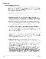
The RDTU PCB provides seven LED indicators to show the status of RDTU: Busy or Idle
condition, Alarm status, and Synchronization status. See Table 6-2 for the function of each status
LED.
shows the LED locations.Busy LED (BSY)—Turns on when one or more RDTU
channels (lines) are in use. Also, when the RDTU does not receive the far end 1.544 mbs carrier
signal, the RDTU will cause the BSY to be on steady.
Alarms are used to indicate potentially serious telephone network problems. Example: when
monitoring a T1 network, if a Blue or Yellow alarm is indicated, it can be concluded that there is a
cable fault or some other serious transmission impairment.
♦
Frame Alarm (FALM)—This LED turns On steady if the RDTU has not achieved
synchronization or when the span cable is not connected.
♦
Multi-Frame Alarm (MFALM)—LEDs turn On steady if the RDTU receives the 1.554 mbs T1
carrier from the far end, but has not achieved Frame synchronization or when the span cable is
not connected. Also, if the RDTU is set for SF and the far end is sending ESF (or vice versa),
the MFALM LED will be On steady.
♦
Red Alarm (FALM and MFALM)—When FALM and MFALM are both On steady, a Red
alarm condition exists. This indicates that the RDTU does not detect a proper carrier signal
(1.544 mbs T1) on its receive pair and the RDTU is not synchronized. When the Red alarm
condition exists, the RDTU should turn the BSY LED On steady and attempt to send a Yellow
alarm signal (RDTU YALM LED flashes) to the far end T1 circuit.
♦
Yellow Alarm (YALM)—When the far end network or CPE T1 does not detect the RDTU
transmitted 1.544 mbs T1 carrier signal on its receive pair the far end T1 sends a Yellow alarm
signal pattern to the RDTU—the RDTU should turn on the YALM LED (the YALM repeats
the signal it receives from the far end—flashing or steady). If the RDTU does not receive the
far end carrier signal, the RDTU sends the Yellow alarm signal to the far end and causes the
BSY and YALM LEDs to flash.
♦
Blue Alarm (BALM)—The Blue alarm, also known as the Alarm Indication Signal (AIS), is
detected by the RDTU. This signal is sent by the Far End Network equipment to RDTU when
it loses the carrier from a Network T1 circuit (other than RDTU). This signal assures that the
RDTU maintains synchronization when there is a problem between two Network Nodes. The
RDTU BALM also lights if the far end sends a Blue alarm signal during loop back. The RDTU
sends a Blue alarm signal when loop-back test is being performed.
Synchronization LEDs
♦
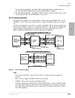
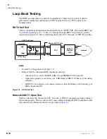
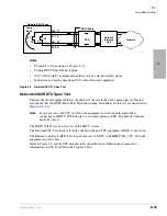
Primary Synchronization (PSYNC) LED (see
) – If one RDTU PCB is
assigned as the Primary Timing T1 PCB in Program *42, the PSYNC LED of this RDTU PCB
flashes when it is synchronized with the far end T1 span line clock provider. If the Primary
RDTU is not synchronized with the clock provider, the PSYNC LED will be On steady. The
SSYNC LED of the Primary sync RDTU PCB should always be Off. The Primary sync RDTU
PCB synchronizes the RTCU (time-switch) to the clock signal it receives from the T1 span
circuit to which it is connected. The RTCU then synchronizes the DK PCM talk path (time-
switch) to the far end PCM talk path.
♦
Secondary Synchronization (SSYNC) LED – If an RDTU PCB is assigned as the Secondary
time T1 PCB in Program *42, its SSYNC LED will be On steady (standby mode) when the
DK is synchronized to the Primary T1 clock provider. In the event of a loss of Primary
synchronization (when 4 out of 12 consecutive frame timing bits are in error) the DK switches
from synchronizing to the Primary RDTU span line clock to the span line clock connected
RDTU designated as the Secondary Timing Reference. When the DK is synchronized to the
Summary of Contents for Strata AirLink DK40i
Page 22: ...Introduction Related Documents Media xx Strata DK I M 6 00 ...
Page 48: ...DK14 Installation DK14 Wiring Diagrams 1 26 Strata DK I M 6 00 ...
Page 220: ...DK424 Installation Remote Cabinet Installation Instructions 5 68 Strata DK I M 6 00 ...
Page 262: ...DK424i Configuration Primary Reserve Power Cabinet Hardware 6 42 Strata DK I M 6 00 ...
Page 450: ...Universal Slot PCB Wiring Option Interface PCB Wiring Diagrams 10 42 Strata DK I M 6 00 ...
Page 592: ...Peripheral Installation Enhanced 911 Service E911 12 84 Strata DK I M 6 00 ...
Page 616: ...ACD Installation Spectrum Electronic Wall Boards 13 24 Strata DK I M 6 00 ...
Page 634: ...Fault Finding Fault Isolation Flowcharts 14 18 Strata DK I M 6 00 ...
Page 704: ...ISDN Interfaces ISDN Disconnect Cause Code 16 54 Strata DK I M 6 00 ...


